Charging control device for a storage battery

a control device and storage battery technology, applied in the direction of secondary cell servicing/maintenance, hybrid vehicles, electrochemical generators, etc., can solve the problems of affecting the deterioration of the storage battery, the inability to accurately grasp the charge state and the storage battery to deteriorate, so as to suppress the progress of deterioration of the lead storage battery

Inactive Publication Date: 2011-02-01
SUBARU CORP
View PDF7 Cites 4 Cited by
  • Summary
  • Abstract
  • Description
  • Claims
  • Application Information

AI Technical Summary

Benefits of technology

[0010]In consideration of the circumstances described above, an object of the present invention is to provide a charging control device for a storage battery which is capable of reducing the effect of an accumulated error occurring when a state of charge of the storage battery is estimated on the basis of a value obtained by integrating a charge and discharge current of the storage battery over a long time period, thereby suppressing overcharging and deep discharge such that the advancement of deterioration of the storage battery is suppressed.
[0012]According to the present invention, the target state of charge is set on the basis of the elapsed time after the storage battery is installed in the vehicle such that the target state of charge increases as the elapsed time increases, and therefore the effect of an accumulated error included in the state of charge can be absorbed by the increase in the target state of charge. As a result, an accumulated error occurring during estimation of the state of charge is unlikely to affect control of the charging voltage applied to the storage battery, and therefore overcharging and deep discharge can be suppressed such that the advancement of deterioration of a lead storage battery can be suppressed.

Problems solved by technology

However, when the current value is integrated continuously over a long time period, an accumulated error increases such that the state of charge determined by the calculation gradually diverges from the actual storage battery state of charge, and therefore, the state of charge of a lead storage battery cannot be grasped accurately.
As a result, overcharging and deep discharge increase, causing the lead storage battery to deteriorate.
However, with the technique disclosed in the above document, a lithium ion storage battery or the like, in which variation in the terminal voltage of the storage battery and variation in the state of charge appear substantially synchronously, is unlikely to be affected by an accumulated error.
In a storage battery such as a lead storage battery, on the other hand, in which a delay is likely to occur during convergence of the terminal voltage depending on the polarization, it is extremely difficult to estimate the open circuit voltage within a limited time period.

Method used


Image

  • Charging control device for a storage battery
  • Charging control device for a storage battery
  • Charging control device for a storage battery

Examples


Embodiment Construction

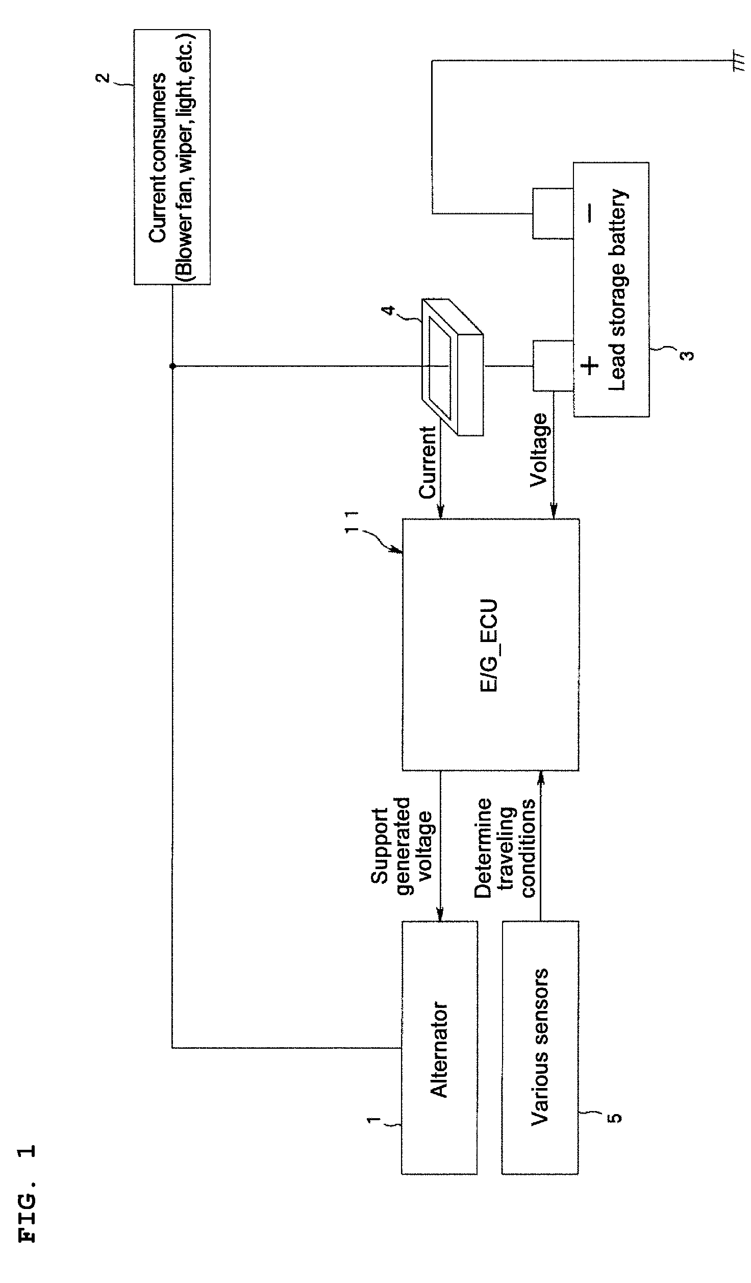
[0019]An embodiment of the present invention will be described below on the basis of the drawings. FIG. 1 is a block diagram showing a vehicle power system.

[0020]The reference numeral 1 in the drawing denotes an alternator serving as a power generator installed in a vehicle, which is driven by an engine, not shown in the drawing, to output generated power. The generated power of the alternator 1 is supplied to a routinely employed current consumer, current consumer means 2 having a comparatively large load, and a lead storage battery 3. Note that the current consumer means 2 include any device that applies a comparatively large electric load of a predetermined value or more to the lead storage battery 3, such as a blower fan, a wiper motor, a light bulb, and a rear defogger.

[0021]Meanwhile, the reference numeral 11 denotes an engine control unit (to be referred to hereafter as “E / G_ECU”) for controlling the entire engine. The E / G_ECU 11 controls the entire engine, including fuel inj...


PUM


Abstract

One of first through fourth target state of charge levels, which are set at values that increase gradually over time, is selected on the basis of an ON / OFF state of a specific current consumer installed in the vehicle and a state of charge immediately preceding an engine stoppage. A target state of charge is set on the basis of the selected target state of charge level and an elapsed time after the lead storage battery is installed in the vehicle, whereupon the target state of charge is compared with the actual state of charge of the lead storage battery. The lead storage battery is charged in accordance with the comparative result.

Description

CROSS-REFERENCE TO RELATED APPLICATIONS[0001]The disclosure of Japanese Patent Application No. 2007-289949, filed on Nov. 7, 2007 including the specification, drawings and abstract is incorporated herein by reference in its entirety.BACKGROUND OF THE INVENTION[0002]1. Field of the Invention[0003]The present invention relates to a charging control device for a storage battery, which controls a charging voltage applied to a storage battery in accordance with at least a state of charge of the storage battery.[0004]2. Description of the Related Art[0005]During conventional storage battery management control for improving fuel efficiency, the state of the storage battery must be monitored to detect overcharging and the like early.[0006]Typical well-known methods of estimating a state of charge include a method of calculating the state of charge from an internal resistance value and an electromotive force, a method of calculating the state of charge using the specific gravity of an electr...

Claims


Application Information

Patent Timeline
Patent Type & Authority Patents(United States)
IPC IPC(8): H02J7/00B60V1/20B60K1/00
CPCH01M10/06H01M10/44H01M10/0525H01M10/446Y02E60/126Y02T10/7011Y02T10/7016Y02E60/10Y02T10/70
Inventor TAKEUCHI, MOTOHIRO
Owner SUBARU CORP
Why Eureka
Try Eureka