Display cell structure and electrode protecting layer compositions

a technology of display cell and composition, applied in static indicating devices, instruments, transportation and packaging, etc., can solve the problems of image bistability degradation, display may have inferior image contrast and bistability, and great difficulties in adopting this approach, so as to ensure reproducibility, consistency and ease of fine tuning, the effect of increasing the effect of voltage applied

Active Publication Date: 2011-02-01
E INK CORPORATION
View PDF16 Cites 100 Cited by
  • Summary
  • Abstract
  • Description
  • Claims
  • Application Information

AI Technical Summary

Benefits of technology

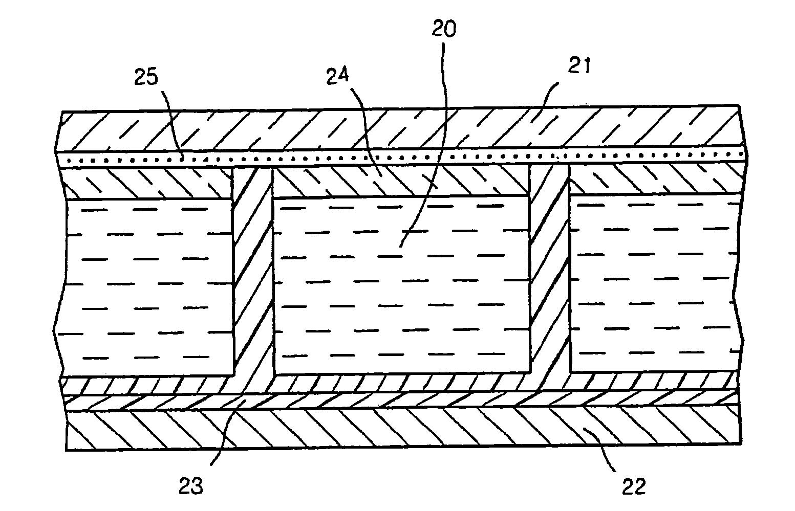
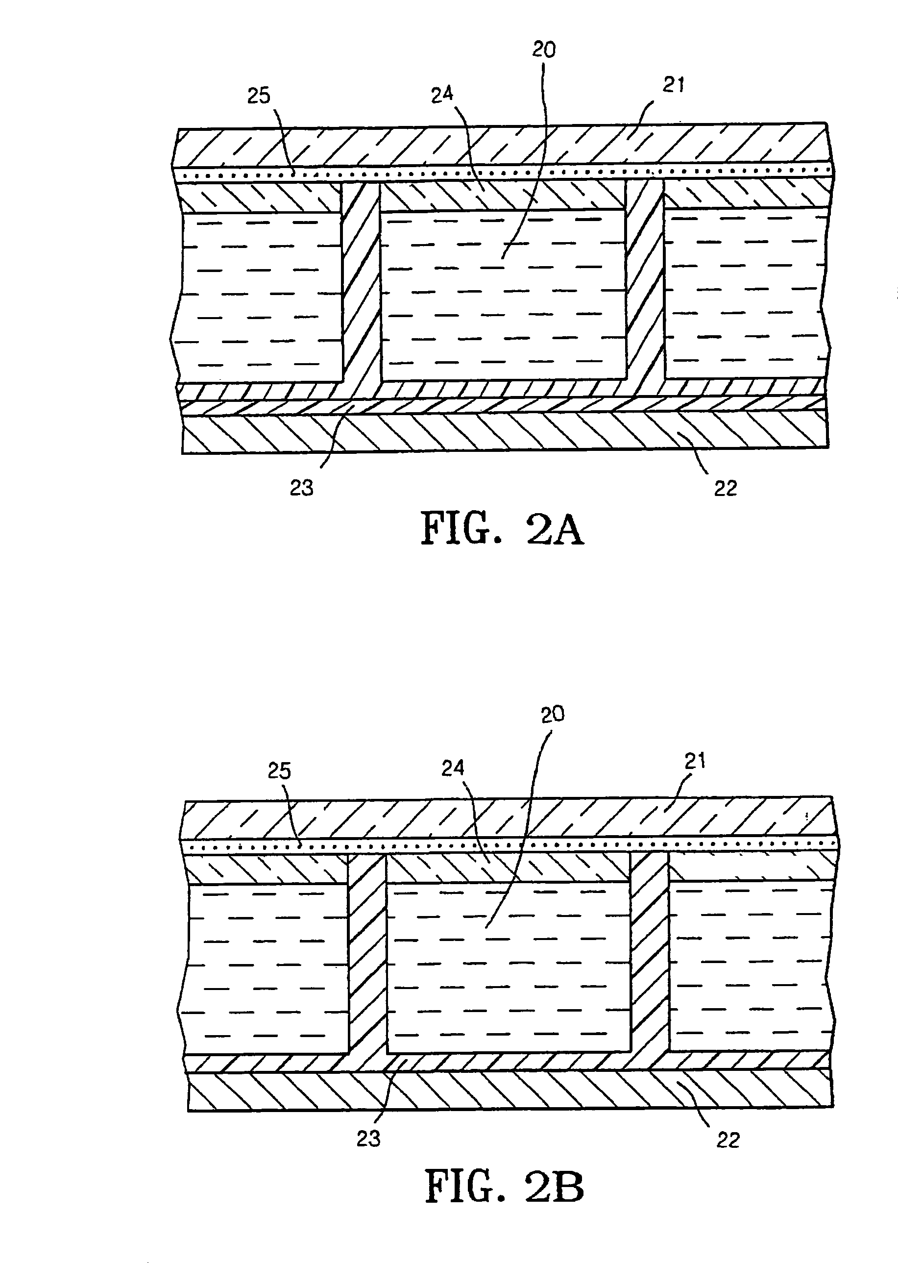
[0015]The present invention relates to compositions of display cell structure and / or electrode protecting layer(s) for improving the performance of a display device.
[0016]More specifically, it has been found that the performance of an electrophoretic display may be improved by forming the display cell structure and / or electrode protecting layer(s) from a composition comprising a polar oligomeric or polymeric material. Such a polar oligomeric or polymeric material may be selected from the group consisting of oligomers or polymers having at least one of the groups such as nitro (—NO2), hydroxyl (—OH), carboxyl (—COO), alkoxy (—OR wherein R is an alkyl group), halo (e.g., fluoro, chloro, bromo or iodo), cyano (—CN), sulfonate (—SO3) or the like. The polar oligomeric or polymeric material has to be compatible with other components in the composition and can be easily processed by simple mixing.
[0021]The resistivity of the display cell structure and / or the electrode protecting layer(s) may be in the range of about 107 to about 1012 ohm cm, thus providing good electric insulation properties.
[0023]The second aspect of the invention is directed to a method for improving the performance of an electrophoretic display which method comprises forming display cell structure and / or electrode protecting layer(s) from a composition as described above.
[0025]The present invention provides a solution to the problems outlined in the Background section of the application. First of all, the present invention involves a one phase system to produce a clear display cell structure and / or the electrode protecting layer(s). The resistance of the display cell structure and / or the electrode protecting layer(s) has a linear relationship with the concentration of the polar oligomeric or polymeric material in the composition, thus ensuring reproducibility, consistency and ease of fine tuning the electrical resistance of the display cell structure and the electrode protecting layer(s) formed. Secondly, the electrical resistance of the display cell structure and / or the electrode protecting layer(s) may be controlled to be in the same range or lower than that of the electrophoretic fluid, thus eliminating the reverse bias problem and increasing the effectiveness of the voltage applied. The present invention, furthermore, is superior over other approaches, including the pre-drive waveform approach, to eliminate reverse bias as it is batch-consistent which results in higher process tolerance during manufacture. Without reverse bias, much simpler driving waveform could be used to increase the display update rate. With higher effective voltage, high switching rate can also be achieved. More importantly, the composition of the present invention is easy to compound and is suitable for a wide variety of display applications.

Problems solved by technology

For all types of electrophoretic displays, image bistability is one of the most important issues.
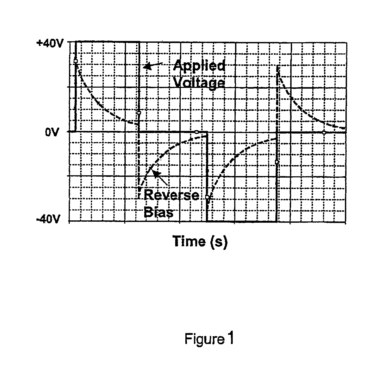
However in certain cases, the image bistability may degrade due to reverse bias.
As a result, the display may have inferior image contrast and bistability.
However, it also acknowledges that there are great difficulties in adopting this approach to achieve the volume resistivity of about 1010 ohm cm required for an adhesive layer used in an electrophoretic display.
Most conductive fillers which may be incorporated into a dielectric material are not transparent and require tedious grinding or milling to be uniformly dispersed into the composition for the display cell structure and polymer layer(s).
Aggregation of the filler particles may also results in an undesirable effect such as poor image uniformity, mottling or, sometimes, short circuit of the display.
In the case of microcup-based electrophoretic displays, incorporation of conductive filler particles into the composition of the microcup structure or the electrode protecting layer(s) tends to cause problems in the manufacture of the microcups.
Defective microcups may be resulted from insufficient or non-uniform degree of photoexposure during the microcup forming process (e.g., microembossing or photolithographic exposure).
Moreover, if the particle size of the filler particles is relatively large as compared to the degree of surface roughness or thickness of the layer comprising the particles, damage on the embossing shim or the conductor film (such as ITO / PET) during embossing may be observed, particularly when the hardness of the conductive filler is higher than that of the shim material or conductor film used.
Optically, the two-phase system often causes a change of the appearance of the polymer structure, such as increased opacity.
Furthermore, a system based on a percolation network often requires the loading of the low resistance filler to be over, but still close to, the percolation threshold, at which stage the filler particles are close enough to touch each other but still not enough to dominate the resistance of the system.
In practice, formulating such a system to achieve an exactly desired level of electrical property with consistency can be difficult because the success of the system would depend on a variety of factors, such as the aggregation structure and exact loading of the filler particles and the amount of impurity that comes with the filler material.

Method used


Image

  • Display cell structure and electrode protecting layer compositions
  • Display cell structure and electrode protecting layer compositions
  • Display cell structure and electrode protecting layer compositions

Examples


examples

[0075]The following examples are given to enable those skilled in the art to more clearly understand and to practice the present invention. They should not be considered as limiting the scope of the invention, but merely as being illustrative and representative thereof.

preparation 1

Synthesis of a Reactive Protective Colloid Rf-amine

[0076]

[0077]17.8 Grams of Krytox® methyl ester (DuPont, MW=about 1780, g=about 10) was dissolved in a solvent mixture containing 12 g of 1,1,2-trichlorotrifluoroethane (Aldrich) and 1.5 g of α,α,α-trifluorotoluene (Aldrich). The resultant solution was added drop by drop into a solution containing 7.3 g of tris(2-aminoethyl)amine (Aldrich) in 2 gm of α,α,α-trifluorotoluene and 30 g of 1,1,2-trichlorotrifluoroethane over 2 hours with stirring at room temperature. The mixture was then stirred for another 8 hours to allow the reaction to complete. The IR spectrum of the crude product clearly indicated the disappearance of C═O vibration for the methyl ester at 1780 cm−1 and the appearance of C═O vibration for the amide product at 1695 cm−1. Solvents were removed by rotary evaporation followed by vacuum stripping at 100° C. for 4-6 hours. The crude product was then dissolved in 50 ml of the PFS2 solvent (perfluoropolyether from Solvay Sol...

preparation 2

Microencapsulation of Pigment in HT200

[0079]8.93 Grams of Desmodur® N3400 aliphatic polyisocyanate (from Bayer AG) was dissolved in 4.75 g of acetone (99.9%, from Burdick & Jackson) and homogenized for 10 seconds with a rotor-stator homogenizer (IKA ULTRA-TURRAX T25, IKA WORKS) at ambient temperature. To the resultant solution, 13.61 g of TiO2 (R706, from DuPont) was added and homogenized for 2 minutes. To the resultant TiO2 dispersion, a solution containing 1.42 g of 1,5-pentanediol (BASF), 0.30 g of triethanolamine (99%, Dow), 2.75 g of polypropylene oxide (MW=725, from Aldrich) and 1.25 g of acetone was added and homogenized for 30 seconds. 0.37 Grams of a 2% dibutyltin dilaurate (Aldrich) solution in acetone was then added and homogenized for 1 minute and 30 seconds. In the final step, 50 g of HT-200 (Solvay Solexis) containing 2.25 g of Rf-amine4900 (prepared according to Preparation 1 above) was added and homogenized for 4 minutes. The resultant microparticle dispersion was th...


PUM

PropertyMeasurementUnit
resistivityaaaaaaaaaa
glass transition temperatureaaaaaaaaaa

Abstract

The invention is directed to compositions of display cell structure and electrode protecting layers for improving the performance of display devices. The composition comprises a polar oligomeric or polymeric material having a glass transition temperature below about 100° C., and the resulting display cells or electrode protecting layer have an average crosslinking density of below about 1 crosslink point per 80 Dalton molecular weight.

Description

[0001]This application claims priority to U.S. provisional application Nos. 60 / 720,188, filed Sep. 23, 2005, and 60 / 762,821, filed Jan. 26, 2006. The contents of both applications are incorporated herein by reference in its entirety.BACKGROUND OF THE INVENTION[0002]1. Field of the Invention[0003]The invention is directed to compositions of display cell structure and electrode protecting layers for improving the performance of display devices.[0004]2. Description of Related Art[0005]The electrophoretic display (EPD) is a non-emissive device based on the electrophoresis phenomenon of charged pigment particles suspended in a solvent. It was first proposed in 1969. The display usually comprises two plates with electrodes placed opposing each other, separated by spacers. One of the electrodes is usually transparent. An electrophoretic fluid composed of a colored solvent with charged pigment particles dispersed therein is enclosed between the two plates. When a voltage difference is impos...

Claims


Application Information

Patent Timeline
Patent Type & Authority Patents(United States)
IPC IPC(8): G02F1/167G02B26/00C09K19/00G09G3/34
CPCC08G18/3814C08G18/5015C08G18/6677C08G18/792G02F1/167C09D175/16Y10T428/1036G02F2202/023Y10T428/1059C09K2323/05C09K2323/03
Inventor ZANG, HONG MEIREN, KANGTAIHOU, JACKWANG, WANHENGCHANG, CHIA-PUCHEN, JING-DENCHEN, YAJUANWANG, FEICHAUG, YI-SHUNG
Owner E INK CORPORATION
Why Eureka
Try Eureka