Measurement device and method, imaging device, and program

a measurement device and measurement method technology, applied in the direction of cameras, instruments, printers, etc., can solve the problems of detection accuracy being reduced, and achieve the effect of simple configuration and reliable measurement of distance between imaging devices and peopl

Active Publication Date: 2011-02-01
ORMON CORP
View PDF13 Cites 4 Cited by
  • Summary
  • Abstract
  • Description
  • Claims
  • Application Information

AI Technical Summary

Benefits of technology

[0007]One or more embodiments of the present invention enables the distance between the imaging device and the human to be reliably measured with a simple configuration.
[0010]Therefore, the distance between the imaging device and the person can be reliably measured with a simple configuration.
[0018]Thus, the red-eye effect continuously occurs even if the illumination light is continuously radiated, whereby the distance between the imaging device and the person can be more reliably measured.
[0021]Therefore, the distance between the imaging device and the person can be reliably measured with a simple configuration.
[0025]Therefore, the distance between the imaging device and the person can be reliably measured with a simple configuration.
[0027]According to one or more aspects of the present invention, the distance between the imaging device and the person can be reliably measured with a simple configuration.

Problems solved by technology

However, the active distance measurement, the passive distance measurement, and the method of measuring the subject distance using an electric wave are not targeted only on humans, and thus the distance may be mistakenly measured if an obstacle other than human cut in between.
Furthermore, when applying a constant association rule irrespective of the difference in person without performing calibration, the detection accuracy may lower due to individual difference in the feature quantity of the face.

Method used


Image

  • Measurement device and method, imaging device, and program
  • Measurement device and method, imaging device, and program
  • Measurement device and method, imaging device, and program

Examples


first embodiment

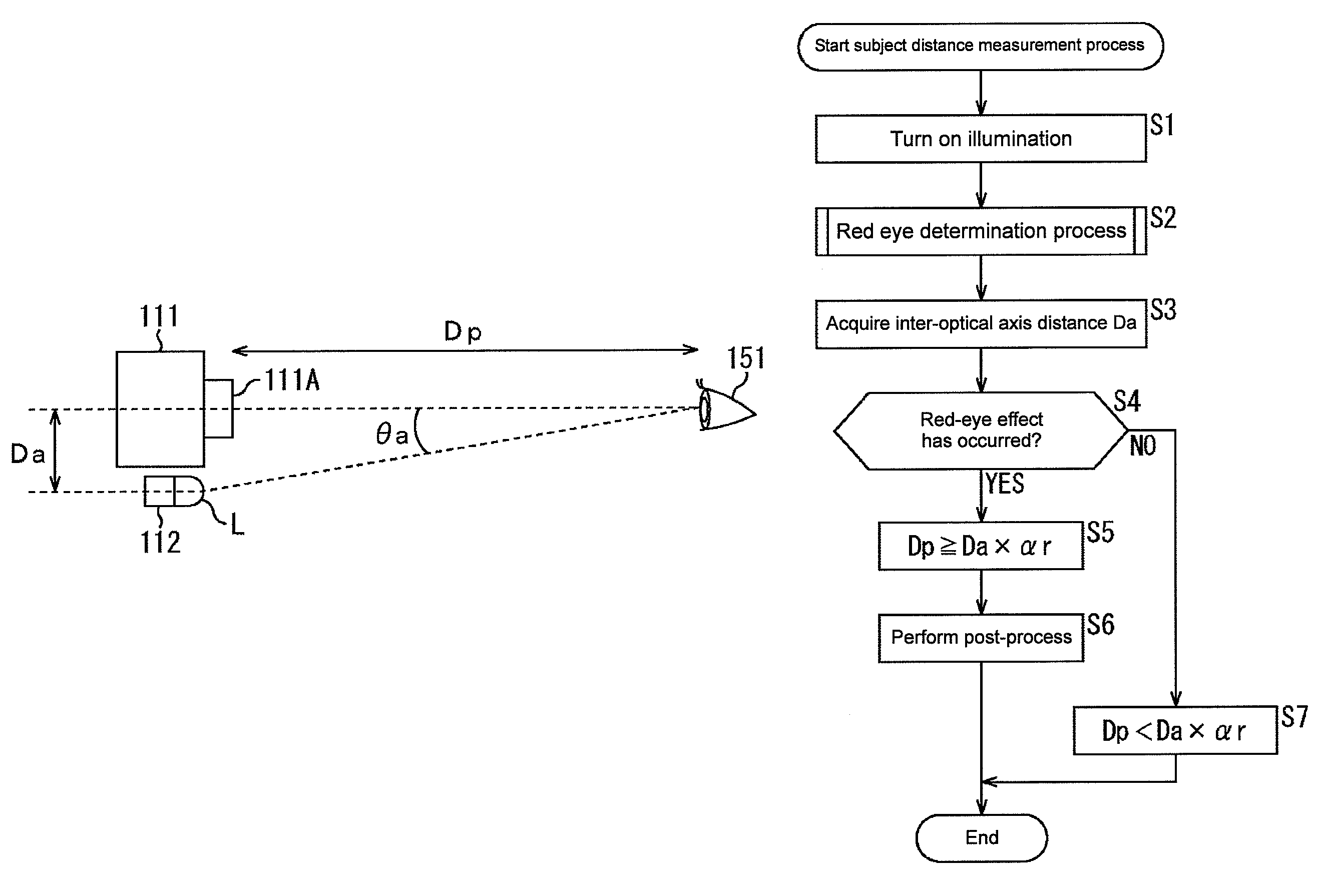
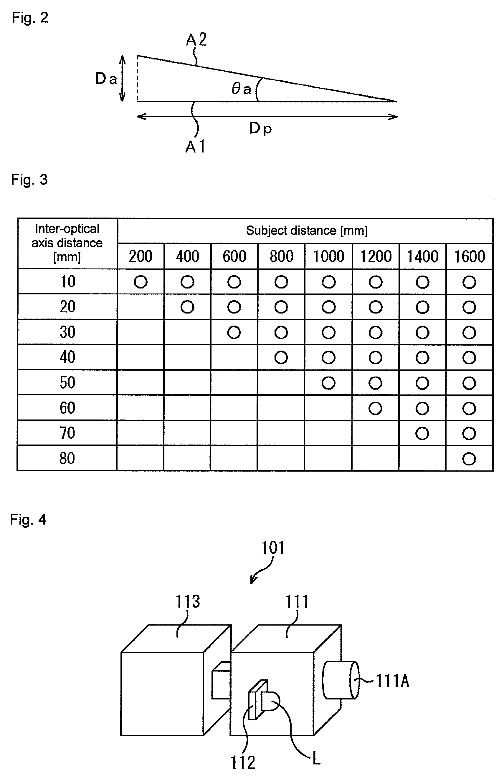
[0076]the present invention will now be described with reference to FIGS. 4 to 8. FIG. 4 shows a schematic view showing a configuration example of an outer appearance of an imaging device 101, and FIG. 5 shows a block diagram showing a functional configuration of the imaging device 101. The imaging device 101 is configured to include an imaging unit 111, an illumination unit 112, and a measurement unit 113.

[0077]The imaging unit 111 is configured by a camera capable of imaging an infrared light using such as a CCD (Charge Coupled Devices) imaging element, a CMOS (Complementary Metal Oxide Semiconductor) imaging element, or a logarithmic conversion-type imaging element. The imaging unit 111 provides an image (hereinafter referred to as an input image) in which a subject is imaged to the measurement unit 113.

[0078]The illumination unit 112 is arranged on the left side facing the front surface of the imaging unit 111 so that a light source L which emits the infrared light configured by...

sixth embodiment

[0226]A sixth embodiment of the present invention will be described with reference to FIGS. 25 to 28. the present invention is obtained by adding a process of determining whether or not to confirm the subject distance when the red-eye effect has not occurred to the second embodiment of the present invention.

[0227]FIG. 25 shows a block diagram showing a function configuration of an imaging device 601. The imaging device 601 is configured to include the imaging unit 111, the illumination unit 112, and a measurement unit 611. The functions including the face direction detecting section 5217 the eye detecting section 121, the red eye determining section 122, the illumination controlling section 221, the outside light information acquiring section 522, and a distance measuring section 621 are realized by having the CPU of the measurement unit 611 execute a predetermined control program. In the figure, same reference numerals are denoted for portions corresponding to FIG. 10 and FIG. 21, ...


PUM


Abstract

A measurement device has a light source, an imaging device, and a distance measuring section The distance measuring section obtains a distance between the imaging device and a person based on a presence of occurrence of a red-eye effect at an eye of the person in an image in which the person irradiated with an illumination light emitted from the light source is imaged by the imaging device, and a distance between an optical axis of the imaging device and the light source.

Description

BACKGROUND OF THE INVENTION[0001]1. Technical Field[0002]The present invention relates to measurement devices and methods, imaging devices, and programs, and in particular to a measurement device and method for measuring the distance between an imaging device and a human, an imaging device, and a program.[0003]2. Related Art[0004]Conventionally, a method of measuring the distance (hereinafter referred to as a subject distance) between a camera and a human typically includes a method (active distance measurement) of irradiating a light ray towards a human and measuring the distance from the time until the reflected light is returned, a method (passive distance measurement) of calculating the distance based on contrast and the like in a photographed image, a method of radiating an electric wave towards a human and measuring the distance from the time until receiving the reflected wave, a method of performing facial recognition of a human in the photographed image and calculating the d...

Claims


Application Information

Patent Timeline
Patent Type & Authority Patents(United States)
IPC IPC(8): G03B3/00
CPCB60R21/01538G02B7/32
Inventor OMOTO, YASUMICHI
Owner ORMON CORP
Why Eureka
Try Eureka