Locking device and a line fitting provided therewith

a technology of locking device and line fitting, which is applied in the direction of fluid pressure sealing joints, screw threaded joints, pipe elements, etc., can solve the problems of vibration excitation and too short a duration for the process of passing over the tooth apex to be possible, so as to prevent any unscrewing and facilitate the production of special nuts

Active Publication Date: 2011-02-08
JPB SYST
View PDF8 Cites 14 Cited by
  • Summary
  • Abstract
  • Description
  • Claims
  • Application Information

AI Technical Summary

Benefits of technology

[0016]According to the invention it has been found that a reversible ratchet system is very effective for preventing any unscrewing as a result of vibrations. The ratchet only disconnects the two components from one another when a spring resistance has been overcome over a sufficient angular distance to reach the point passing over the apex of a ratchet tooth. However the vibratory excitation in one direction or in the other is of too short a duration for this process of passing over the tooth apex to be possible. The process can certainly begin, but it is followed by a springing back to the most stable locking situation.
[0017]By contrast, when an intentional unscrewing is carried out, the operator is not subjected to any feeling of malfunction or disturbance.
[0018]The unscrewing is therefore possible without the operator having to undertake special precautions or actions. He need only engage his tool with the hexagonal or other engagement formation provided on the first component of the screw coupling, and actuate his tool as usual.
[0019]The locking device according to the invention can be designed to be entirely compatible with standard pipe couplings without these requiring modifications other than fixing the device body onto the second component. Preferably, it is the nut which constitutes the second component. It is in fact easier to produce a special nut, in particular in the case of subsequent fitting. Moreover if the nut is equipped with the device, the two end-portions can be completely cleared when they are in the uncoupled state, simply by sliding the nut far enough back along the pipe which carries it, and the locking device no longer forms any obstruction to moving a pipe laterally in relation to the other.

Problems solved by technology

However the vibratory excitation in one direction or in the other is of too short a duration for this process of passing over the tooth apex to be possible.

Method used


Image

  • Locking device and a line fitting provided therewith
  • Locking device and a line fitting provided therewith
  • Locking device and a line fitting provided therewith

Examples


Embodiment Construction

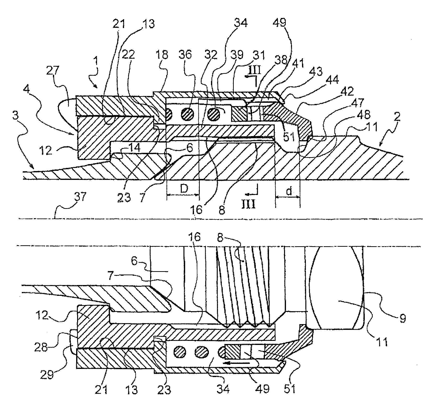
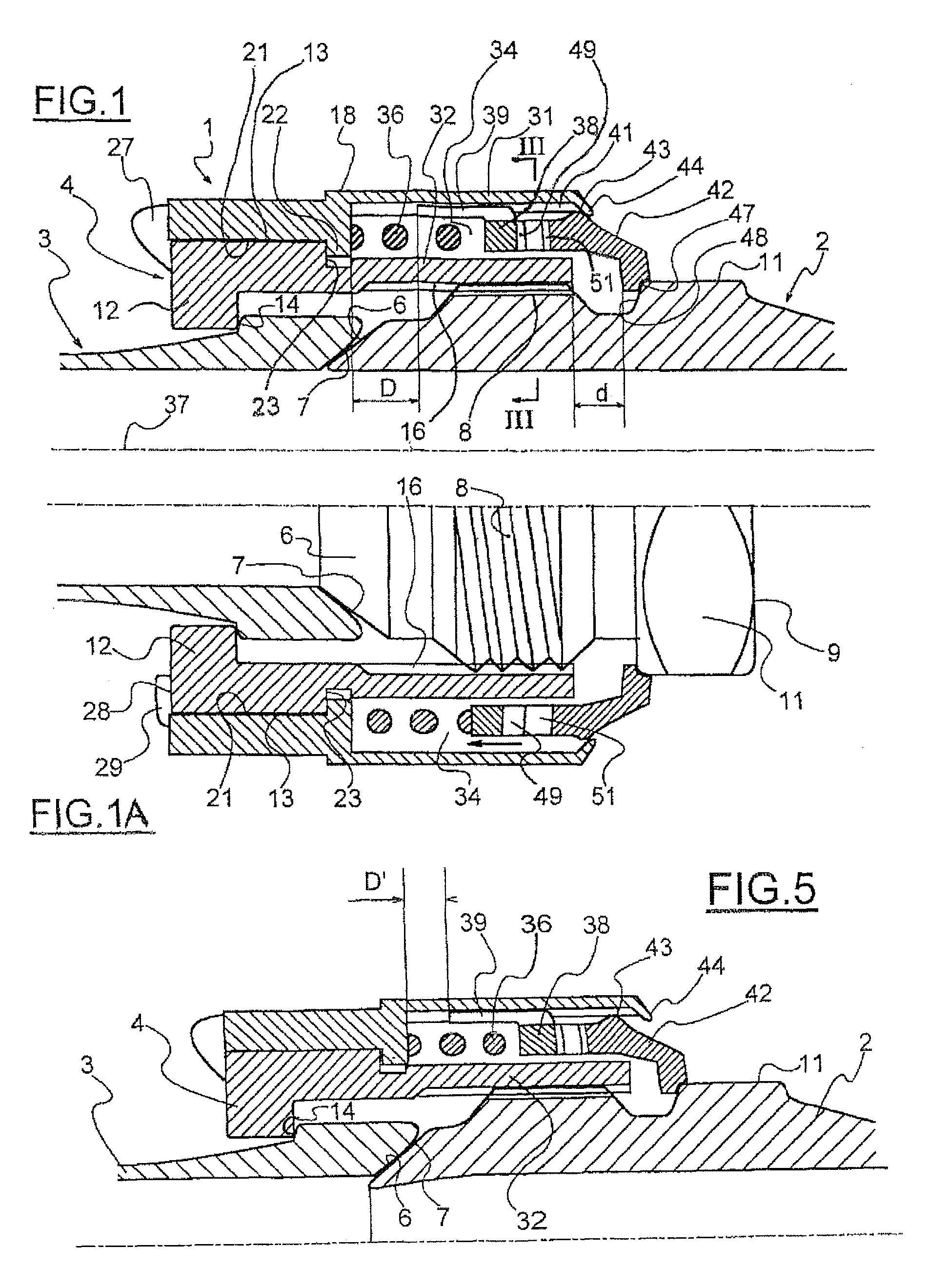
[0030]As shown in FIGS. 1 and 1A, the locking device 1 according to the invention can be adapted to a first pipe coupling comprising a male end-portion 2- or nipple-, firmly attached to a first one of the pipes to be coupled, and a female end-portion 3, which is firmly attached to the second one of the pipes to be coupled, as well as a nut 4.

[0031]The end-portions 2 and 3 comprise at their free end a male seal formation, with an ovoid shape 6 and respectively a female seal formation 7, with a frusto-conical shape, intended to leak-tightly bear on one another. Starting from the ovoid seal formation 6, the nipple 2 comprises an external thread 8 then a flange 9 provided on its periphery with a rotational engagement formation such as a hexagonal formation 11. The formation is distant or separated from the thread 8 of the component 2 in the sense that this formation 11 which will be used for the locking is not constituted by an alteration of the thread such as a flat section or a groove...


PUM


Abstract

A locking device (1) is fixed to a nut (4) and includes a coupling unit (42) insertable into a hexagonal configuration (11) of a spigot end (2) at a reduced axial distance being coupled by mutually interpenetrable gears (49, 51) with a stop unit (38) which axially slides in a body (18) opposite to a compression spring (36). The gears (49, 51) are symmetric and are insertable into each other with a predetermined elastic resistance by the action of compression or loosing torque. The device is embodied in one piece which is mounted by assembling with the nut without affecting the spigot ends (2, 3).

Description

BACKGROUND OF THE INVENTION[0001]1. Field of the Invention[0002]This invention relates to a locking device for two components which are in a mutual screw connection.[0003]This invention also relates to a pipe coupling provided with such a device.[0004]The function of the locking device is to prevent undesirable unscrewing of the two components from each other, in particular in applications where the two components are subject to vibrations or shaking during use.[0005]The invention is more particularly but not limitatively aimed at standardized couplings comprising a nipple at the end of one of the pipes, intended to be pressed into a flaring of the end of the other pipe, by tightening a nut captively mounted on one of the pipes and engaging a thread formed on the other pipe.[0006]2. Description of Related Art[0007]U.S. Pat. No. 6,293,595 B1 describes such a locking device capable of simultaneously engaging, by an axial movement under pressure from a spring, the hexagonal formation o...

Claims


Application Information

Patent Timeline
Patent Type & Authority Patents(United States)
IPC IPC(8): F16L15/00F16L19/00
CPCF16L19/005
Inventor MARC, JEAN PIERREBARRE, BERNARD
Owner JPB SYST
Why Eureka
Try Eureka