Bail type unlocking device for opto-electronic module

an optoelectronic module and unlocking device technology, applied in the field of optical communication, can solve the problems of difficult to be connected to the bail, difficult manufacturing of pins, and unavoidable burrs of sheet metal pieces, and achieve the effect of simple configuration and operation and practical structur

Active Publication Date: 2011-02-08
WUHAN TELECOMM DEVICES
View PDF3 Cites 5 Cited by
  • Summary
  • Abstract
  • Description
  • Claims
  • Application Information

AI Technical Summary

Benefits of technology

[0012]The present invention is mainly for solving the above mentioned shortcomings or disadvantages in the prior art. The present invention provides a bail type unlocking device for an opto-electronic module, which has a practical structure with simple configuration and operation, and the unlocking device is adapted to the requirements for the development of communication apparatus.
[0061]1. The structure of the invention is optimized, the manufacturing of the parts are simplified and the reliability of the parts is improved.
[0063]3. The assembling operation of the module is very simple and the speed of assembly is improved.

Problems solved by technology

The disadvantages or problems of the prior art mainly lie in the following:
The sheet-metal pieces unavoidably have burrs with uncomfortable feelings;
The pin is hard for manufacturing, which is difficult to be connected to the bail;
The slot is hard for manufacturing, the burrs can not be easily removed, and the precision thereof can not be easily controlled etc.

Method used


Image

  • Bail type unlocking device for opto-electronic module
  • Bail type unlocking device for opto-electronic module
  • Bail type unlocking device for opto-electronic module

Examples


Embodiment Construction

[0074]Reference will now be made in detail to the preferred embodiments of the present application. It can be appreciated that various modifications in many different ways can be made to the following illustrative embodiments of the present invention without departing the principle of the present invention disclosed herein. Therefore, the scope of the present invention will in no way be limited to the special embodiments in the following.

[0075]Firstly, description will be made to the structure of the major components of the preferred embodiment of the present invention. It is noted that not all of the following components or its particular constituent parts are necessary for realizing the purpose of the present invention. The following description to the structure of the major components shall not be construed as limiting the protection scope of the present invention.

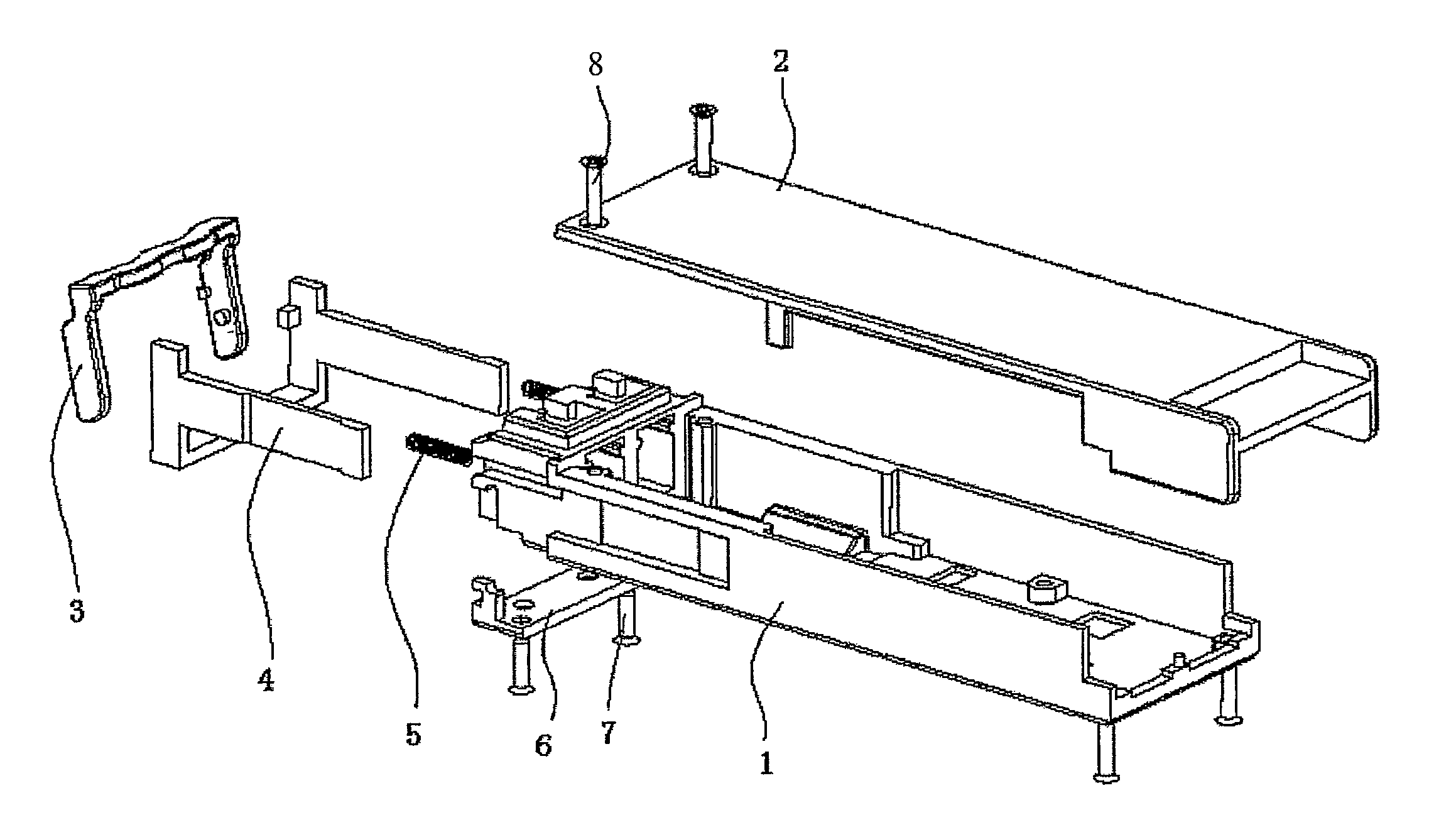
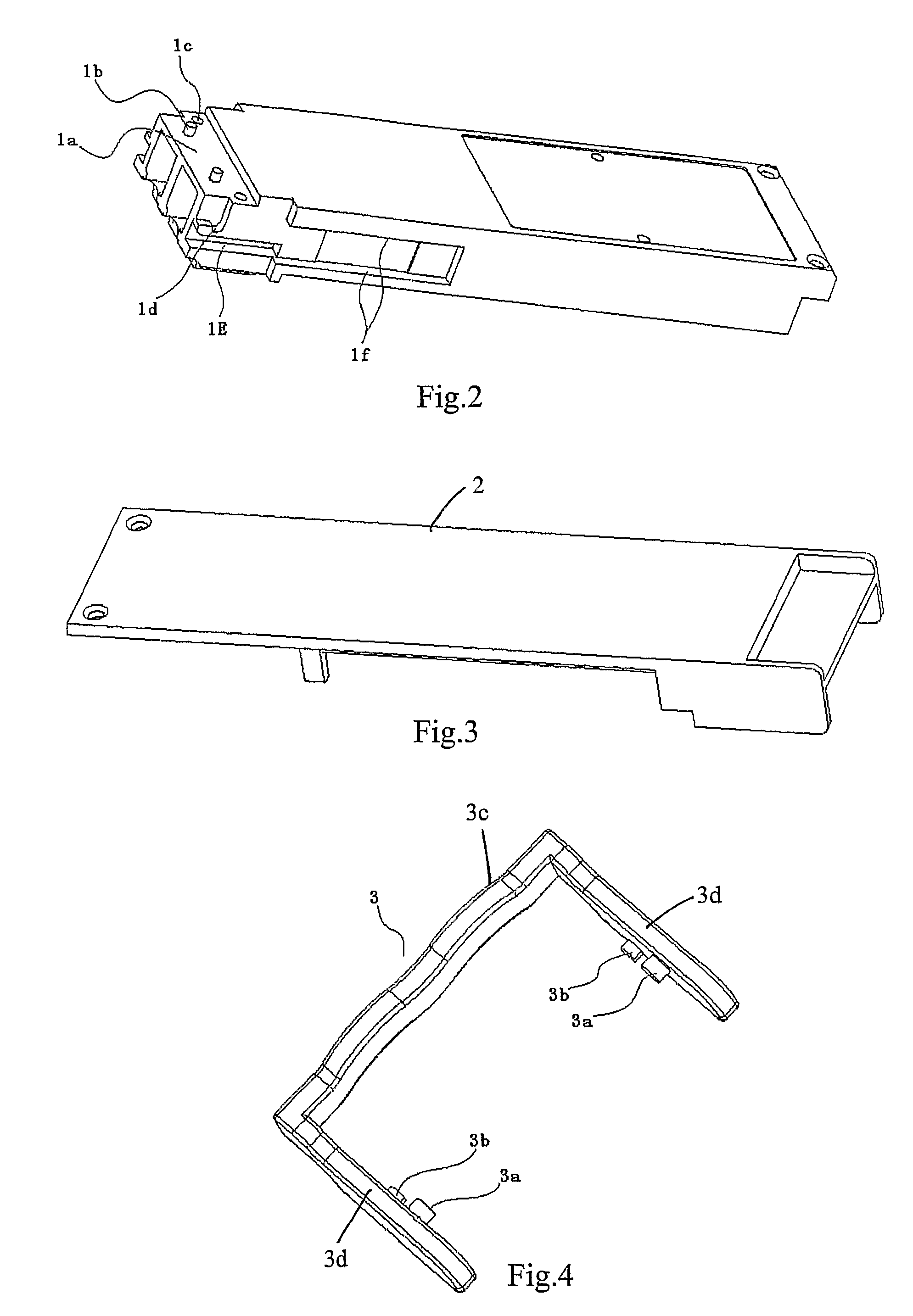
[0076]1. Bottom Housing 1

[0077]As shown in FIG. 2, the bottom housing 1 is provided as a substantially rectangular ch...


PUM


Abstract

A bail type-unlocking device for an opto-electronic module, which pertains to an unlocking device for a hot pluggable type opto-electronic module in the optical communication field. The unlocking device includes: a bottom housing; an operating unit; a latching unit; an elastic element; and a briquetting; wherein: the latching unit is movably engaged with the bottom housing; the elastic element is provided between the latching unit and the bottom housing, and the latching unit can be movable relative to the bottom housing under the elastic force of the elastic element; the operating unit is configured to be engaged with the bottom housing, when an external force from an operator is applied to the operating unit, the operating unit pivots around a pivot axis thereof with respect to the bottom housing to drive the latching unit so that the latching unit can be movable between a locked position and an unlocked position with respect to the bottom housing; and the briquetting is fixed on the bottom housing and engages with the operating unit, when the latching unit is located at the unlocked position, the briquetting restricts the pivot movement of the operating unit around the pivot axis with respect to the bottom housing.

Description

PRIORITY CLAIM[0001]This is a U.S. national stage of application No. PCT / CN2006 / 002981, filed on Nov. 7, 2006. Priority is claimed on the following application(s): Country: China, Application No.: 200620097447.6, Filed: Jun. 29, 2006, the content of which is incorporated here by reference.BACKGROUND OF THE INVENTION[0002]1. Field of the Invention[0003]The present invention pertains to optical communication field. The present invention generally relates to an unlocking device for a hot pluggable type opto-electronic module, and particularly, to a bail type unlocking device for opto-electronic module.[0004]2. Description of the Related Art[0005]Conventionally, the unlocking device used for a hot pluggable opto-electronic module is of push-and-pull or bail type. An unlocking device for SFP (Small Formfactor Pluggable) module generally adopts a push-and-pull or bail type structure; an unlocking device for XFP (10 Gigabit Small Formfactor Pluggable) Module mainly adopts the bail type str...

Claims


Application Information

Patent Timeline
Patent Type & Authority Patents(United States)
IPC IPC(8): G02B6/36
CPCH01R13/6335G02B6/4246G02B6/4292G02B6/4284
Inventor LUO, JIANFENGQUAN, BENQINGWANG, BIAO
Owner WUHAN TELECOMM DEVICES
Why Eureka
Try Eureka