
Auxiliary supporting device of a bicycle

a technology of supporting device and bicycle, which is applied in the direction of sport apparatus, gymnastics, stilts, etc., can solve the problems of bicycles not being able to swing along the imaginary axis direction of the wheel contact surface, and less places where people can exercis

Inactive Publication Date: 2011-02-08
WAN KUO HUI
View PDF20 Cites 6 Cited by
  • Summary
  • Abstract
  • Description
  • Claims
  • Application Information

AI Technical Summary

Benefits of technology

[0011]Another object of the present invention is to propose an auxiliary supporting device of a bicycle, in which the front and rear wheels of the bicycle rotate synchronously so that a user can simulate the exercise of riding a bicycle at a fixed location to accomplish the exercising effect.
[0013]Still yet another object of the present invention is to propose an auxiliary supporting device of a bicycle, in which the bicycle can swing along an imaginary axis (embodied with a main rotating shaft) direction of the wheel contact surface to train a user his sense of balance.
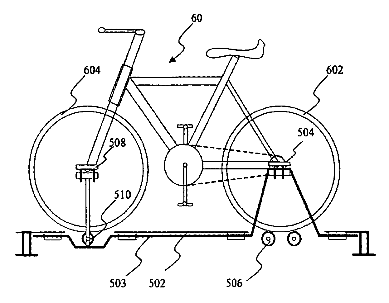
[0014]To achieve the above objects, the present invention proposes an auxiliary supporting device of a bicycle, which comprises a base, two rolling elements and a supporting element. The base is connected with a main rotating shaft having a protruding part, which is engaged with a wheel axle of a rear wheel of a bicycle. The two rolling elements are disposed on the base and located below the protruding part so that partial wheel surface of the rear wheel is located on the rolling element. The supporting element is disposed above the main rotating shaft. The supporting element is engaged with a front wheel of the bicycle. The supporting element includes a rotating element with a rolling element. The front wheel is located on the rolling element. A rotating guide wire is used to connect the rear wheel rolling elements and the front wheel rolling element. When a user sits on the bicycle and moves the pedals, the rear wheel leads the rolling element to roll and further drives front wheel rotate via the rotating guide wire and front wheel rolling element, thereby accomplishing synchronous rotation of the front and rear wheels.

Problems solved by technology

Moreover, because high buildings stand in great numbers in cities, there are less and less places where people can exercise.
This bicycle, however, cannot swing along an imaginary axis direction of the wheel contact surface.

Method used


Image

  • Auxiliary supporting device of a bicycle
  • Auxiliary supporting device of a bicycle
  • Auxiliary supporting device of a bicycle

Examples


Embodiment Construction

[0025]In order to help people achieving the effect of exercise indoors, the present invention proposes an auxiliary supporting device of a bicycle. As shown in FIGS. 4, 5 and 6, an auxiliary supporting device 50 comprises a base 502 with a main rotating shaft 503. The main rotating shaft 503 has a protruding part 504, and a rear wheel 602 of a bicycle 60 is engaged on the protruding part 504. Two rolling elements 506 are disposed on the base 60 and located below the protruding part 504 such that rear wheel 602 of the bicycle 60 is located on the rolling elements 506. The main rotating shaft 503 has also a supporting element508. The supporting element 508 includes a rotating element connected with a rolling element 510 for engaging a front wheel 604 of the bicycle 60 such that front wheel 604 is located on the rolling element 510.

[0026]The main rotating shaft 503 can be either free rotated to let bicycle 60 sway (As shown in FIGS. 7(a) and 7(b), the bicycle 60 can swing along the axl...


PUM


Abstract

An auxiliary supporting device is designed for supporting and fixing a bicycle. When a user rides a bicycle which is set up on this supporting device, the bicycle will neither move forward nor fall down if the user applies the skill of riding bicycle. This device can be used to train a rider for better bicycle controllability or to let user exercise at a fixed location.

Description

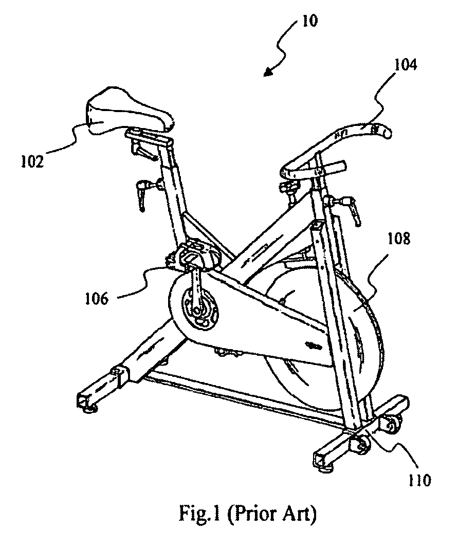
BACKGROUND OF THE INVENTION[0001]1. Field of the Invention[0002]The present invention relates to an auxiliary supporting device of a bicycle and, more particularly, to an auxiliary supporting device of a bicycle for exercise.[0003]2. Description of Related Art[0004]With the progress of science and technology, people become busier and have less time to go out exercising. Moreover, because high buildings stand in great numbers in cities, there are less and less places where people can exercise.[0005]Therefore, many kinds of exercise equipments have sprung up in the market such as exercise bicycles, treadmills, and so on. People can use these equipments to exercise indoors.[0006]In the disclosure of U.S. Pat. No. 6,612,970, an adjustable stationary exercise bicycle is proposed. As shown in FIG. 1, a bicycle 10 comprises a seat 102, handlebars 104, two connected pedals 106 and a wheel 108. All the above components are disposed on a lower frame 110. This bicycle, however, cannot swing al...

Claims


Application Information

Patent Timeline
Patent Type & Authority Patents(United States)
IPC IPC(8): A63B22/06
CPCA63B26/003A63B69/16A63B2069/163A63B2069/165
Inventor WAN, KUO-HUI
Owner WAN KUO HUI
Learn More