Anti-gravity power generation wheel and operation method thereof

An anti-gravity, wheel technology, applied in the direction of wheels, electric components, electromechanical devices, etc., can solve the problems of reducing the power generation capacity of wheels, difficult production and application of wheels, poor power generation capacity, etc., to improve the speed, drive efficiency and power generation. The effect of efficiency

Pending Publication Date: 2022-06-24
ZHONGCI POWER EQUIP (SHENZHEN) CO LTD
View PDF1 Cites 1 Cited by
  • Summary
  • Abstract
  • Description
  • Claims
  • Application Information

AI Technical Summary

Problems solved by technology

However, the weak driving force of the circulating airflow in the wheel on the impeller makes the power generation capacity of this type of wheel poor, and the deformation of the wheel during driving is irregular, and the circulating airflow is easy to form a local vortex inside the wheel, or Multiple airflows that cancel each other further reduce the ability of the wheel to generate electricity, making this type of wheel difficult to put into production applications

Method used


Image

  • Anti-gravity power generation wheel and operation method thereof
  • Anti-gravity power generation wheel and operation method thereof
  • Anti-gravity power generation wheel and operation method thereof

Examples


Embodiment 1

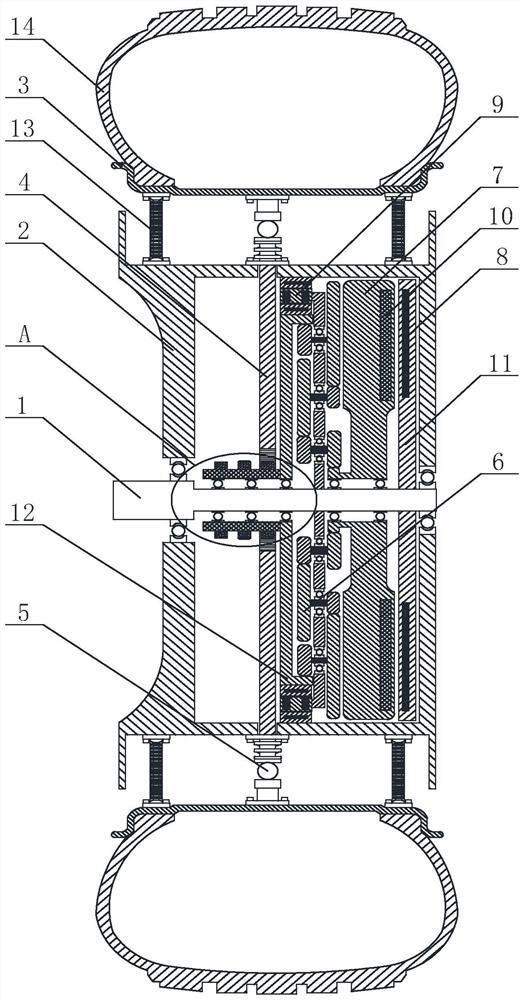
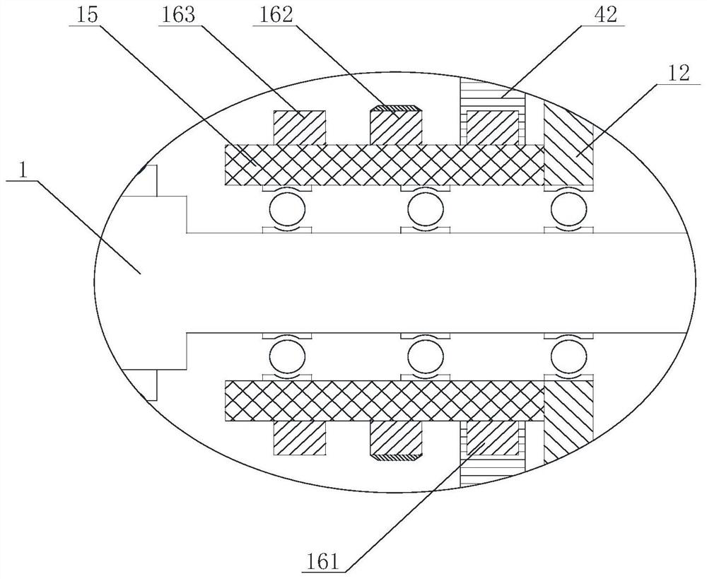
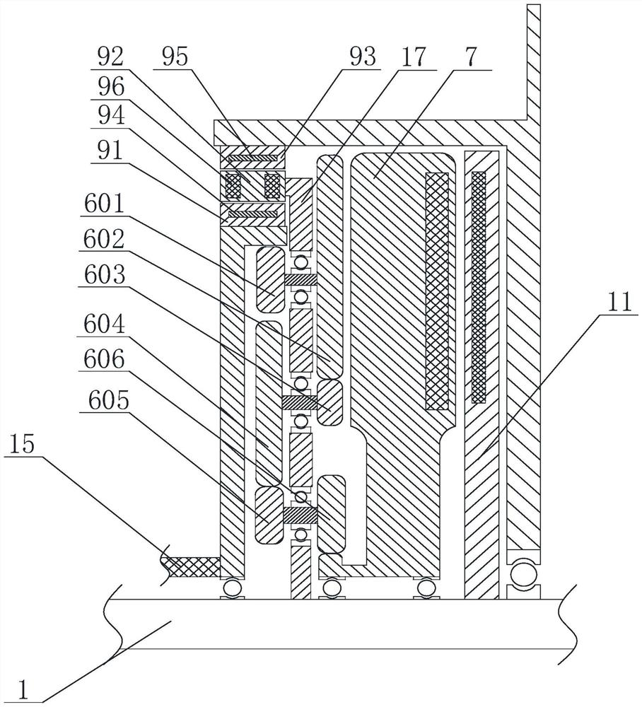
[0050] like Figure 1 to Figure 7The shown anti-gravity power generation wheel includes a main shaft 1 on which a hub 2, a rim 3, a stator and a flywheel rotor 7 are coaxially arranged, and the flywheel rotor 7 can rotate relative to the stator to generate current , the main shaft 1 is sleeved with a ratchet bushing 15 connected to the flywheel rotor 7, the ratchet bushing 15 is provided with n ratchet wheels, wherein n is a positive integer, and the wheel rim 3 is provided with a movable Through the gravity converter 4 of the hub 2, when the wheel rotates until the gravity converter 4 is vertical, the ratchet moves vertically downward relative to the gravity converter 4, and is subject to the gravity converter 4 The drive rotates a certain angle.

[0051] In this technical solution, components such as ratchet bushings and gravity converters are used to push the flywheel rotor to rotate during the running process of the vehicle, thereby realizing power generation during the r...

Embodiment 2

[0060] On the basis of Example 1, as Figure 5 As shown, the adjustment mechanism includes a first sleeve 51 mounted on the inner wall of the rim 3 , the support rod 43 is at least partially located in the first sleeve 51 , and the bottom surface of the first sleeve 51 A first spring 52 is provided on the upper part, and the first spring 52 is connected to the end face of the support rod 43; the side wall of the support rod 43 .

[0061] When the hub moves vertically downward relative to the rim, the adjustment mechanism of the gravity converter in the non-vertical state can allow the support rod to move vertically downward with the hub for a certain distance, or generate a lateral offset during the downward movement. During this process, the position of the support rod in the sleeve changes; after the hub is reset, the support rod returns to the initial position coaxial with the first sleeve again under the action of the first spring and the second spring. In addition, the ...

Embodiment 3

[0063] On the basis of Example 1, as Image 6 and Figure 7 As shown, the adjustment mechanism includes two supports 55 mounted on the inner wall of the rim 3, and a telescopic piece 54 with an adjustable length is hinged on the support 55, and the telescopic piece 54 is connected to the support The end faces of the rods 43 are hingedly connected.

[0064] In one or more embodiments, the telescopic element can be a hydraulic cylinder, the position of the gravity converter can be adjusted by precisely controlling the length of the hydraulic cylinder, one end of the hydraulic cylinder is hinged to the support, and the other end is hinged to the support rod. In one or more embodiments, as Figure 8 As shown, the telescopic element includes a second sleeve 541, and a connecting rod 542 is slidably disposed in the second sleeve. The connecting rod and the second sleeve are connected by a third spring 543 to realize self-adaptive adjustment of the overall length of the telescopic ...


PUM


Abstract

The invention discloses an anti-gravity power generation wheel and an operation method thereof, the wheel comprises a main shaft, a hub, a rim, a stator and a flywheel rotor are coaxially arranged on the main shaft, the flywheel rotor can rotate relative to the stator to generate current, a ratchet shaft sleeve connected to the flywheel rotor sleeves the main shaft, n ratchets are arranged on the ratchet shaft sleeve, n is a positive integer, and n is a positive integer. A gravity converter movably penetrating through the hub is arranged on the rim, and when the wheel rotates till the gravity converter is vertical, the ratchet vertically moves downwards relative to the gravity converter and is driven by the gravity converter to rotate by a certain angle. The gravity of the automobile is larger than the traction force in the running process of the automobile, the distance of several centimeters of the automobile moving downwards due to the gravity is converted into rotation of the flywheel rotor relative to the stator through the suspension type hub, the gravity converter, the ratchet wheel and the ratchet wheel shaft sleeve so as to generate electric energy, and therefore energy conversion in the running process of the automobile is achieved. The power generation efficiency of the wheels is improved, and the cruising ability of the electric automobile is greatly prolonged.

Description

technical field [0001] The invention relates to the technical field of wheel devices, in particular to an anti-gravity power generation wheel and an operation method thereof. Background technique [0002] With the development of electric vehicles, their endurance has been greatly improved, but compared with fuel vehicles, electric vehicles are still plagued by cruising range and supplementary power. [0003] The current electric vehicle braking energy recovery system can provide a certain range of battery life for the electric vehicle in motion, but this system has limitations, it can only replenish a certain amount of electricity for the electric vehicle when the vehicle decelerates and brakes , and when the vehicle is accelerating, driving normally, and driving at high speed, it cannot provide electricity and supplementary electricity for electric vehicles. During the driving process of the vehicle, compared with the deceleration and braking operations, the time for vehic...

Claims


Application Information

Patent Timeline
Patent Type & Authority Applications(China)
IPC IPC(8): H02K7/18H02K7/07H02K7/116H02K7/02B60B19/00
CPCH02K7/1846H02K7/07H02K7/116H02K7/02H02K7/025H02K7/006B60B19/00
Inventor 罗业富钱凤军
Owner ZHONGCI POWER EQUIP (SHENZHEN) CO LTD
Why Eureka
Try Eureka