
Method of making luminance enhancement optical substrates with optical defect masking structures

a technology of optical substrates and structures, applied in the field of optical substrates having a structured surface, can solve the problems that predefined irregularities introduced may not mask all types of defects, and achieve the effects of reducing the effect of structural defects on perceived image quality, enhancing luminance or brightness, and reducing prominen

Active Publication Date: 2011-02-08
UBRIGHT OPTRONICS CORP
View PDF43 Cites 13 Cited by
  • Summary
  • Abstract
  • Description
  • Claims
  • Application Information

AI Technical Summary

Benefits of technology

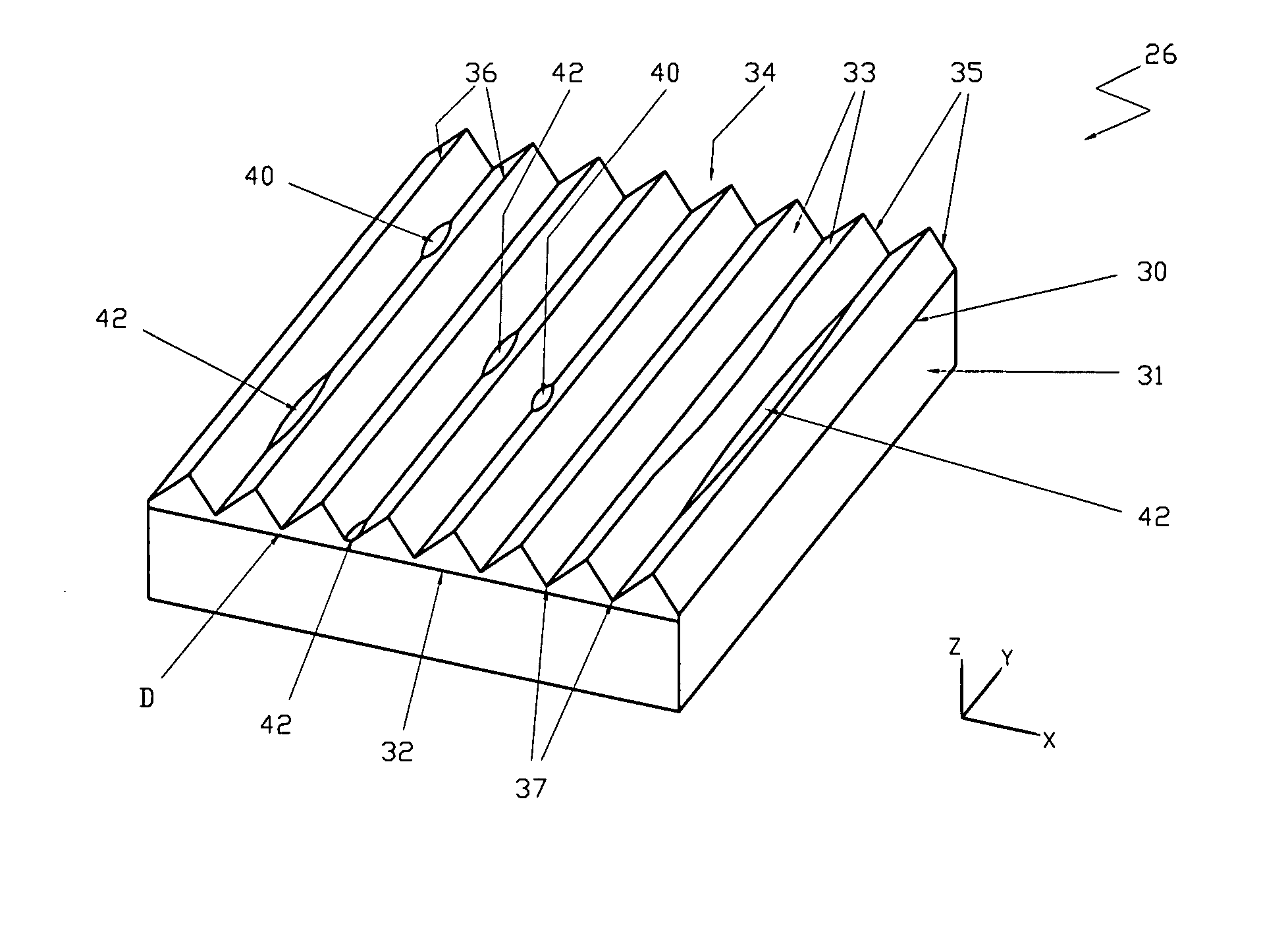
The present invention is directed to a luminance enhancement film comprising an optical substrate (which may be supported by a base layer) that possesses a structured surface that enhances luminance or brightness and reduces the effects of structural defects on perceived image quality. In accordance with the present invention, user perceivable optical cosmetic defects caused by manufacturing or handling can be masked by introducing defined structural irregularities in the optical substrate. The optical cosmetic defects would be blended with the optical effects introduced by such structural irregularities, with the cosmetic defects reduced in prominence in the display image, to effectively hide, mask or largely reduce certain cosmetic defects.

Problems solved by technology

The predefined irregularities introduced may not mask all types of defects present in an actual luminance enhancement substrate.

Method used


Image

  • Method of making luminance enhancement optical substrates with optical defect masking structures
  • Method of making luminance enhancement optical substrates with optical defect masking structures
  • Method of making luminance enhancement optical substrates with optical defect masking structures

Examples


Embodiment Construction

The present description is of the best presently contemplated mode of carrying out the invention. This invention has been described herein in reference to various embodiments and drawings. This description is made for the purpose of illustrating the general principles of the invention and should not be taken in a limiting sense. It will be appreciated by those skilled in the art that variations and improvements may be accomplished in view of these teachings without deviating from the scope and spirit of the invention. The scope of the invention is best determined by reference to the appended claims.

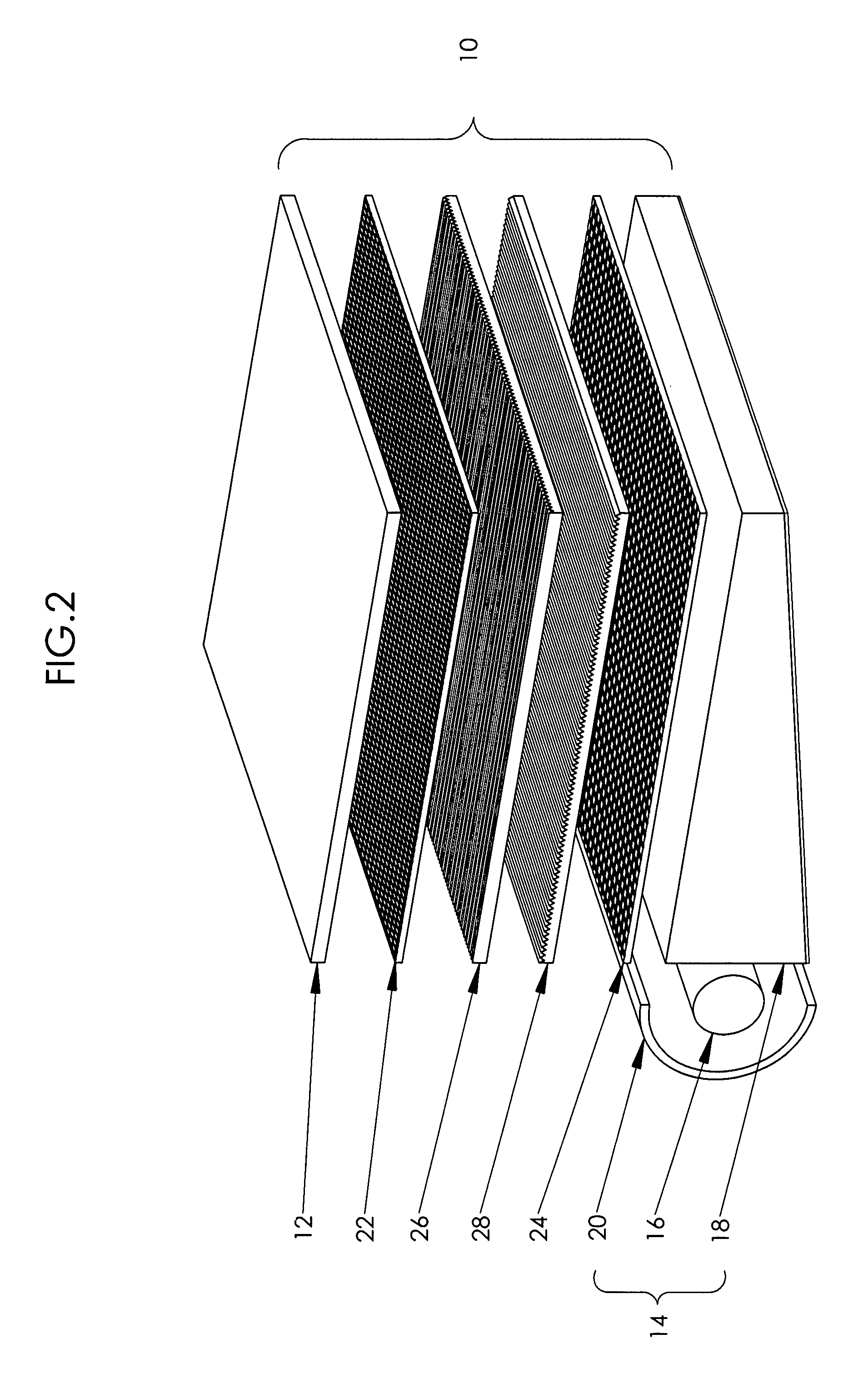
The present invention is directed to luminance enhancement substrate having an optical substrate (which may be supported by a base layer) that possesses a structured surface that enhances luminance or brightness and reduces the effects of structural defects on perceived image quality. In accordance with the present invention, user perceivable optical cosmetic defects caused by manufacturi...


PUM

PropertyMeasurementUnit
thicknessaaaaaaaaaa
lengthaaaaaaaaaa
lengthaaaaaaaaaa

Abstract

An optical substrate possesses a structured surface that enhances luminance or brightness and reduces the effects of structural defects on perceived image quality. User perceivable image cosmetic defects caused by manufacturing or handling, can be masked by introducing structural irregularities in the optical substrate, which may be non-facet flat sections or in-kind to the defects. Optical defects caused by non-facet flat sections in the prism structure of the optical substrate (e.g., flat-bottom valleys with a certain valley bottom thickness above the base layer, and / or flat-top peaks, and / or openings in the optical substrates that expose flat sections of underlying base layer) can be masked by providing distributed in-kind non-facet flat sections (e.g., flat-bottom valleys, and / or flat-top peaks, and / or openings exposing sections of underlying base layer), to diffuse the prominence of the original defects with the introduced irregularities.

Description

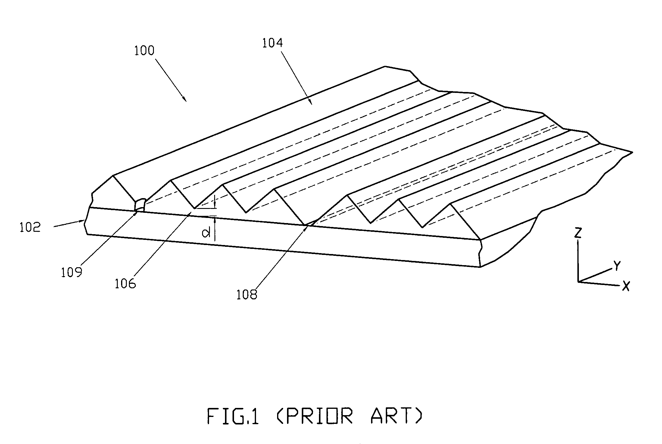
BACKGROUND OF THE INVENTION1. Field of the InventionThe present invention relates to optical substrates having a structured surface, particularly to optical substrates for brightness enhancement, and more particularly to brightness enhancement substrates for use in flat panel displays having a planar light source.2. Description of Related ArtFlat panel display technology is commonly used in television displays, computer displays, and handheld electronics (e.g., cellular phones, personal digital assistants (PDAs), etc.). Liquid crystal display (LCD) is a type of flat panel display, which deploys a liquid crystal (LC) module having an array of pixels to render an image. In backlight LCDs, brightness enhancement films use prismatic structures to direct light along the viewing axes (i.e., normal to the display), which enhances the brightness of the light viewed by the user of the display and which allows the system to use less power to create a desired level of on-axis illumination.Here...

Claims


Application Information

Patent Timeline
Patent Type & Authority Patents(United States)
IPC IPC(8): B29D11/00
CPCG02B5/045G02B6/0053G02F1/133606G02F1/133504Y10T428/24355G02F1/133611G02F2001/133507G02F2001/133607G02F1/133507G02F1/133607G02B5/02G02B6/00G02F1/1335
Inventor WANG, KONG-HUALIN, CRAIGKO, DANIEL YAW-CHUNG
Owner UBRIGHT OPTRONICS CORP
Learn More