Enlarged display for a camera viewfinder

a viewfinder and enlarged technology, applied in the field of accessories of cameras, can solve the problems of not offering the photographic quality and flexibility of the interchangeable lens slr, not providing a device or method to use the standard viewfinder, and not being able to frame or compose images, etc., to achieve the effect of easy viewing an imag

Inactive Publication Date: 2011-02-08
KUSS MARK L
View PDF13 Cites 22 Cited by
  • Summary
  • Abstract
  • Description
  • Claims
  • Application Information

AI Technical Summary

Benefits of technology

[0022]Yet another object of the invention is to provide

Problems solved by technology

The digital SLR cameras have a display screen for reviewing images in memory, but no ability to frame or compose an image on the display screen before capturing the image.
However, the cameras utilizing the far view screens do not offer the photographic quality and flexibility of the interchangeable lens SLR.
The problem with this type of camera 400 design is that the image 105 may only be seen through this viewfinder 625.
Thus, the prior tends to replace the existing viewfinder with an electronic

Method used


Image

  • Enlarged display for a camera viewfinder
  • Enlarged display for a camera viewfinder
  • Enlarged display for a camera viewfinder

Examples


Embodiment Construction

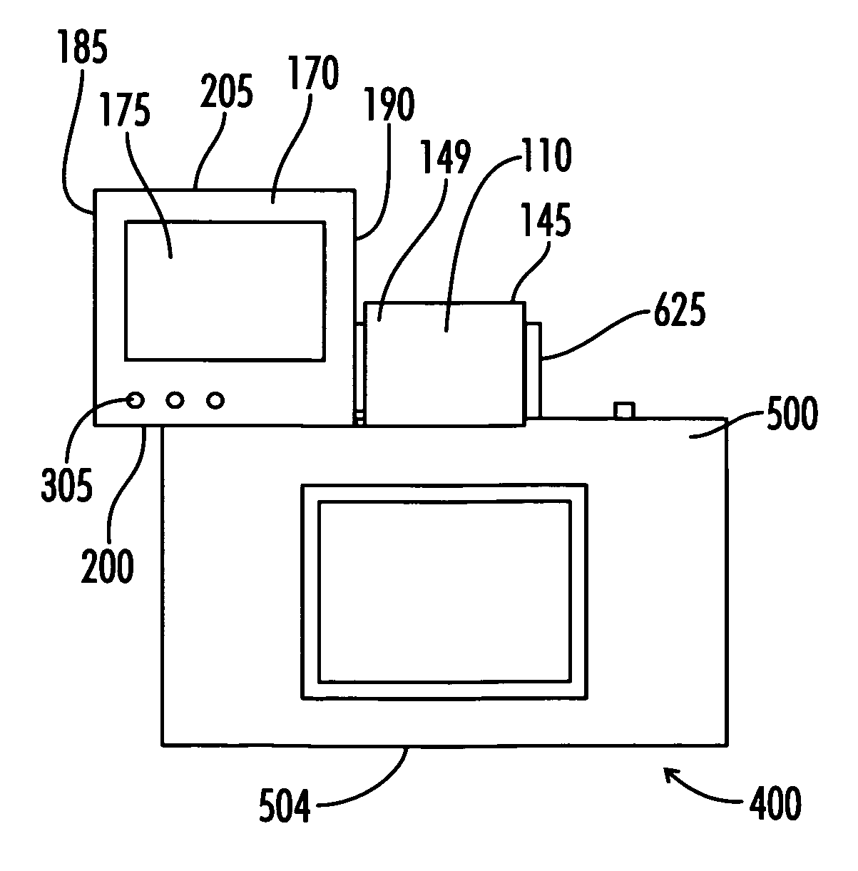
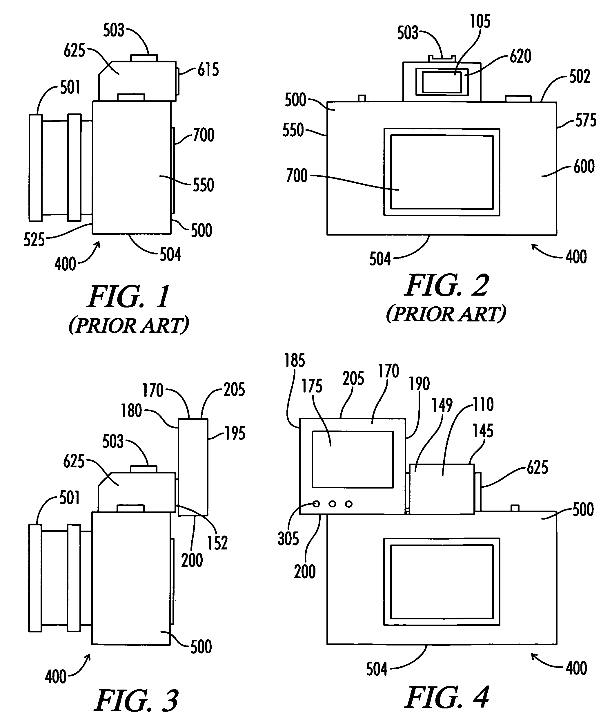
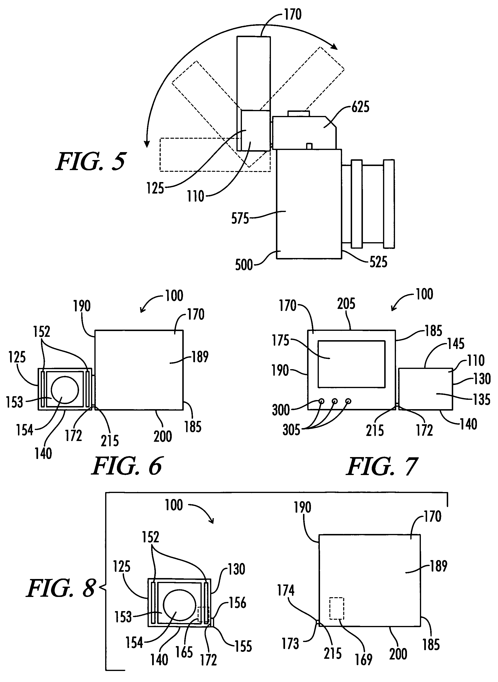
[0037]As shown in FIGS. 3 through 11 of the drawings, one exemplary embodiment of the present invention is generally shown as an image transporting apparatus 100. FIGS. 3 through 5, 10, and 11 show the image transporting apparatus mounted on a camera body 500 and FIGS. 6 through 9 show the image transporting apparatus 100 by itself. The image transporting apparatus 100 is constructed to have both an image capture device 110 and an image display device 170. Each of these is addressed in turn.

[0038]The image capture device 110 includes generally a front 120, a right side 130, a left side 125, a back 135, a top 145, and a bottom 140 constructed with a plastic or other material shell 149 surrounding the image capture device 110. At least one image sensor 160 is utilized to receive and capture the image 105 from the viewfinder 625 through an image viewing window 154. When mounted to the camera 400, the image viewing window 154 is positioned within the viewfinder monitoring location 615 f...


PUM


Abstract

A remote viewfinder display device using an image capturing device including a sensor positioned at an existing camera's viewfinder in communication with a remote display device which shows the viewfinder image at an alternative location to allow a photographer to frame the photograph in the viewfinder when the viewfinder is in an inaccessible or inconvenient position. The display can also provide a larger image for easier viewing. The remote viewfinder display device eliminates the constraints of a near eye view finder and provides for the ability to frame pictures with the alternatively positioned viewable screen or display independent of the existing camera's limited viewfinder position.

Description

[0001]This application claims priority to and is a continuation of U.S. application Ser. No. 11 / 120,097, filed May 2, 2005, now abandoned.BACKGROUND[0002]1. Field of the Invention[0003]The present invention relates generally to the field of camera accessories. In particular, the present invention relates to an add on image capturing device for an existing camera where the device allows the image presented in the existing camera's viewfinder to be visible from a remote position.[0004]2. Description of the Known Art[0005]As will be appreciated by those skilled in the art, modern film cameras use two basic types of viewfinders: separate lens set and through the lens viewing. Cameras using the separate lens sets are commonly referred to as viewfinder window cameras and through the lens viewing cameras are referred to as single lens reflex or SLR.[0006]With the onset of digital cameras, a new type of viewfinder became common. The near view viewfinders were complimented with a far view sc...

Claims


Application Information

Patent Timeline
IPC IPC(8): G03B13/02H04N5/222
CPCG03B13/02H04N5/23293H04N23/531
Inventor KUSS, MARK L.
Owner KUSS MARK L
Why Eureka
Try Eureka