
Waste management

a technology for managing waste and waste, applied in the field of waste management, can solve the problems of unfavorable environmental protection, unfavorable environmental protection, and requiring regular service, and achieve the effect of effective and reliable vacuum-operated managemen

Inactive Publication Date: 2011-02-15
EHNVAK AB
View PDF12 Cites 7 Cited by
  • Summary
  • Abstract
  • Description
  • Claims
  • Application Information

AI Technical Summary

Benefits of technology

"The invention is a vacuum-operated system for managing waste in a decentralized mode, close to where it is generated. The system provides an improved method of managing waste collected in a decentralized mode, offering cost-effective and user-friendly operation. The system includes an inlet unit connected to a vacuum tank through a vacuum pipe, and the vacuum pressure is maintained during the entire operational phase of the system. The invention offers advantages such as requiring low vacuum pressure for secure discharge operation, being mechanically robust, flexible with regard to the number of connected inlet units, and adaptable to different types of buildings and waste applications."

Problems solved by technology

By virtue thereof the systems are not very cost efficient unless they are used in applications where they are in very frequent operation.
They are sensitive to technical disturbance, thereby requiring regular service.

Method used


Image

  • Waste management
  • Waste management
  • Waste management

Examples


first embodiment

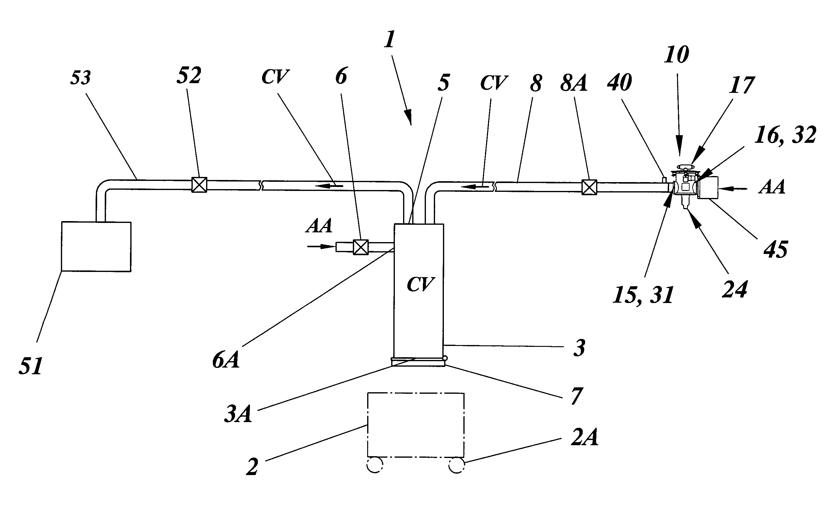
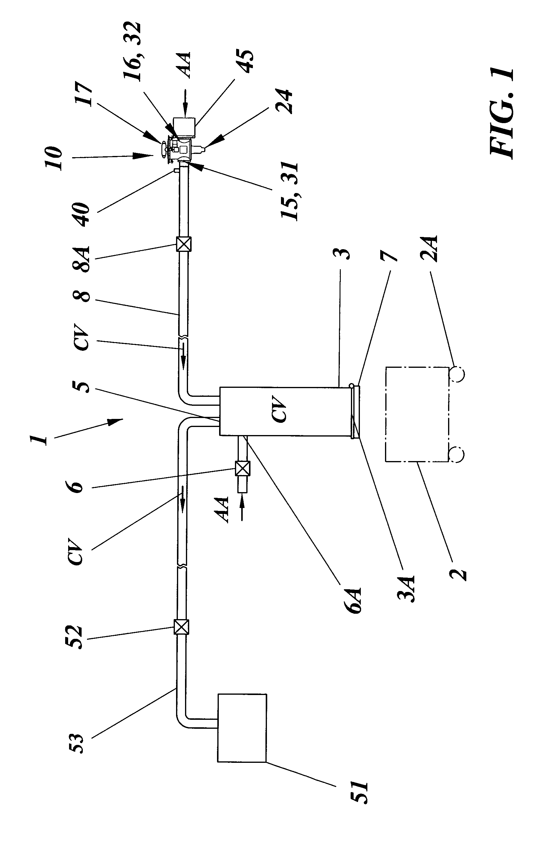
[0040]A first exemplifying embodiment of the invention is shown in FIG. 1 and an exemplary application thereof is shown in FIG. 8. This first embodiment relates to a domestic waste management system 1 that comprises a separate temporary storage volume 3 for the collected waste. The storage volume has a bottom opening 3A that is closed by an openable lid 7 and through which collected waste may be removed intermittently and in a controlled manner from the storage volume 3 by gravity. Said waste may be discharged into a suitable container 2 preferably having wheels 2A to facilitate further transfer of the collected waste. The storage volume 3 is connected through a vacuum inlet 5, a vacuum pipe 53 and a charging vacuum valve 52 to a vacuum pressure source 51 delivering a moderate vacuum pressure CV that depends upon the actual application, such as the number of the later described inlet units 10 connected to the storage volume 3 and the length of the likewise later described waste pipe...

second embodiment

[0060]To the left in this drawing figure is illustrated a multi-story building 104 like the one in FIG. 9, having a waste management system 301 that is similar to the invention. Here, the temporary storage volume consists of the waste shaft 303A and a separate waste tank 303B to which it is connected, and is illustrated integrated in the mobile vacuum waste transport system 80 connected thereto for performing the emptying. The waste tank 303B is likewise illustrated having a waste discharge valve 307 that opens into a waste transport pipe 302 of the mobile vacuum waste transport system 80 and through which waste transport vacuum TV is applied to the storage volume 303A, 303B from the vacuum truck 81.

[0061]Specifically, this drawing figure clarifies that the basic waste management of the invention is not restricted to any specific emptying method or system for discharging collected waste from the temporary storage volume. Instead, the inventive system may be used with most of the pre...


PUM


Abstract

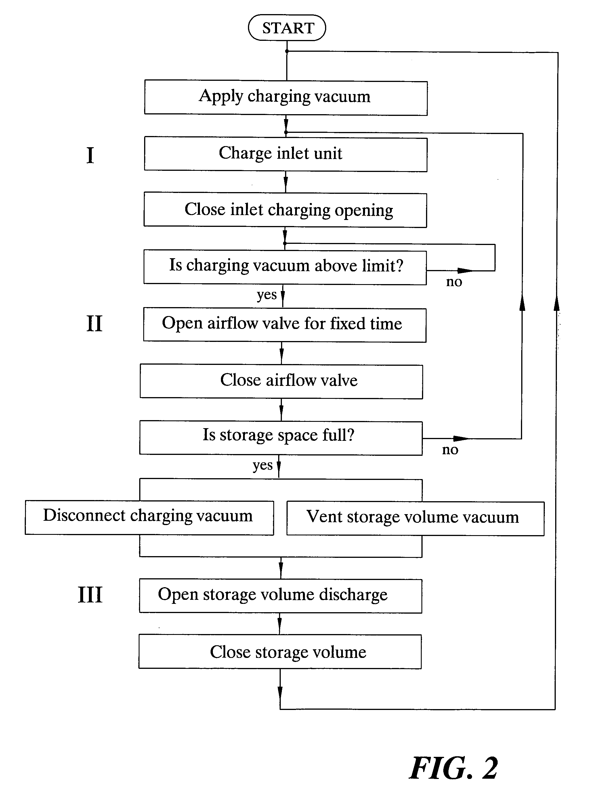
Waste material that is introduced into waste inlet units (10) is managed by connecting the inlet units to a temporary storage volume (3) for charging the storage volume with the waste and by controlled, intermittent opening of the storage volume for the removal of accumulated waste therefrom. Specifically, waste is introduced into each inlet unit during an inlet charging phase; shaft charging vacuum (CV) is applied to the storage volume and is maintained continuously therein except when waste is removed from the storage volume; and the charging vacuum and atmospheric air (AA) is intermittently communicated to the inlet unit to charge the storage volume with the introduced waste.

Description

TECHNICAL FIELD[0001]The present invention relates generally to waste management, and specifically relates to the management of domestic waste material by means of vacuum.BACKGROUND[0002]The handling of domestic waste using traditional vacuum systems has for many years been increasingly centralized both with regard to the introduction of waste into the vacuum system and to the collection and disposal of the waste. In other words, waste is collected further and further away from the place where it is generated and the system vacuum is used both for discharging temporarily stored waste and for transporting said waste to collection centrals or collection points.[0003]For certain types of waste, such as kitchen waste containing a high-liquid fraction of mostly biological waste, it is desirable to dispose of the waste very close to the place were it is generated. In such situations it has been common, not least in households but also for processing waste from restaurants and commercial o...

Claims


Application Information

Patent Timeline
Patent Type & Authority Patents(United States)
IPC IPC(8): A47L5/38
CPCB65F5/005B09B3/00
Inventor KIHLSTROM, CHRISTER
Owner EHNVAK AB
Learn More