
Low profile graphic display device and method

a graphic display device and low-profile technology, applied in the field of backlit graphic display devices, can solve the problems that none of the display units disclosed are suitable for mounting around the user's neck, and achieve the effects of simple battery replacement operation, low maintenance, and convenient us

Inactive Publication Date: 2011-12-29
PODD GEORGE O
View PDF12 Cites 18 Cited by
  • Summary
  • Abstract
  • Description
  • Claims
  • Application Information

AI Technical Summary

Benefits of technology

[0019]As noted in the '944 and '832 Applications, there is a perceived need in the art(s) for enhanced visibility of graphic elements not only for marketable applications, but also for reasons of safety. For example, as has been demonstrated in the '944 and '832 Applications, enhanced visibility of graphic elements as displayed upon vehicles may help overcome low visibility driving conditions, such as snow, rain, darkness and / or fog. With increased visibility of specific graphic elements on a vehicle, other motorists can better see dedicated information, particularly in adverse weather conditions or low visibility driving conditions.
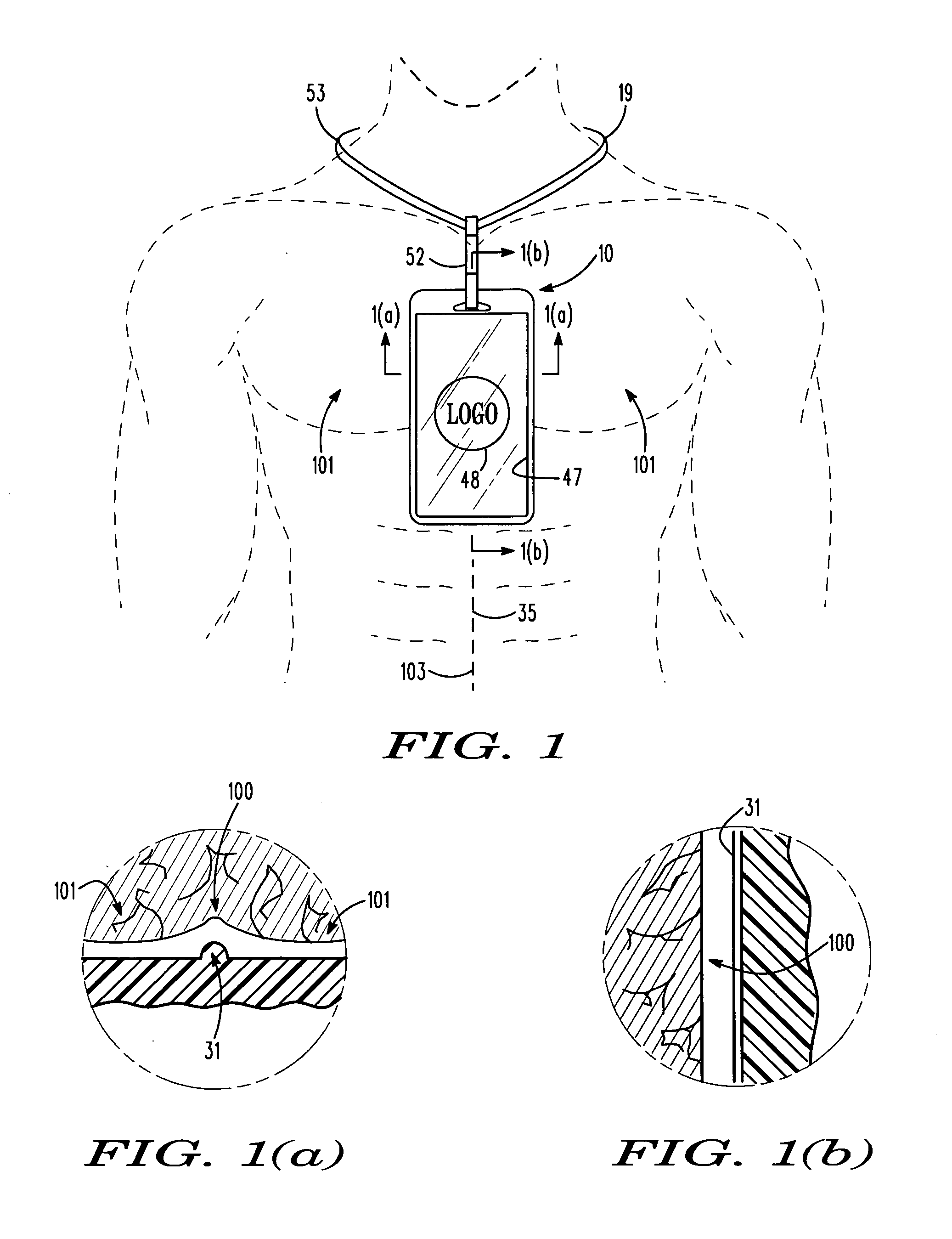
[0021]The graphic display device according to the present invention incorporates a light guide panel for directing edge-received light anteriorly through a translucent graphics panel. The graphic display device further incorporates a lanyard assembly for enabling the user to wear the graphic display device upon one's person as hung from the neck to allow themed graphics, such as words, logos and / or symbols, to be readily visible.
[0023]A product of this invention may be easy to use, require low maintenance and operate within control module settings and functional parameters. For example, a motion sensor, a light sensor and / or a timer switch can be used to make all necessary or desired adjustments, so that the user does not have to use or address the on / off switch once a desired operational mode is set. The user may have an option to change a mode setting. A battery recharge capability, particularly if automatic, allows the user to not be concerned with replacing or manually recharging batteries. A removable battery module provides a simple battery replacement operation.
[0024]A product according to this invention can be manufactured and operate within a range of reasonable costs, based on potential market applications. An interchangeable translucent graphic panel and layer assembly allows the light guide illumination assembly components to provide standardized back light. Thus, custom printing of clear plastic sheet material minimizes the cost, the inventory and the production time. Sensors optimize product function, provide a user-friendly product and prolong battery life during use. There can be a battery recharge capability with, for example a solar panel option, to prolong battery life.
[0025]With a product according to this invention, consumers may obtain value added attributes of increased visibility for their specific needs. Also, the consumer is able to use the graphic display device according to the present invention and benefit from improved user features and cost effective operation. The graphic display device may include a static or constant display or illumination and / or a dynamic or animated graphic display or illumination.

Problems solved by technology

While the above referenced patent disclosures are directed to illuminated display devices, none of the display units disclosed are suitable for mounting around a user's neck for displaying graphics upon the chest or otherwise in anterior adjacency to the user's torso.

Method used


Image

  • Low profile graphic display device and method
  • Low profile graphic display device and method
  • Low profile graphic display device and method

Examples


Embodiment Construction

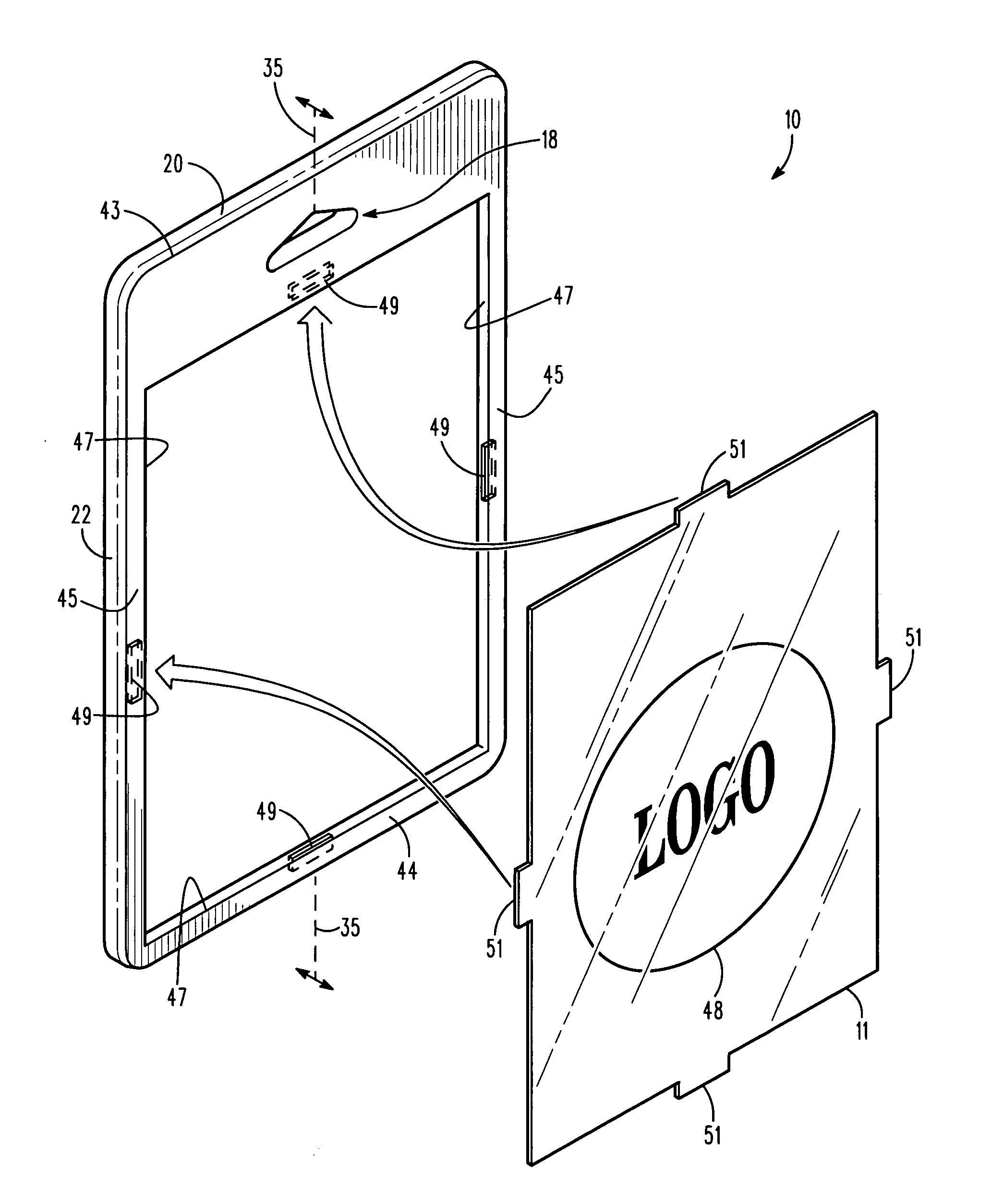
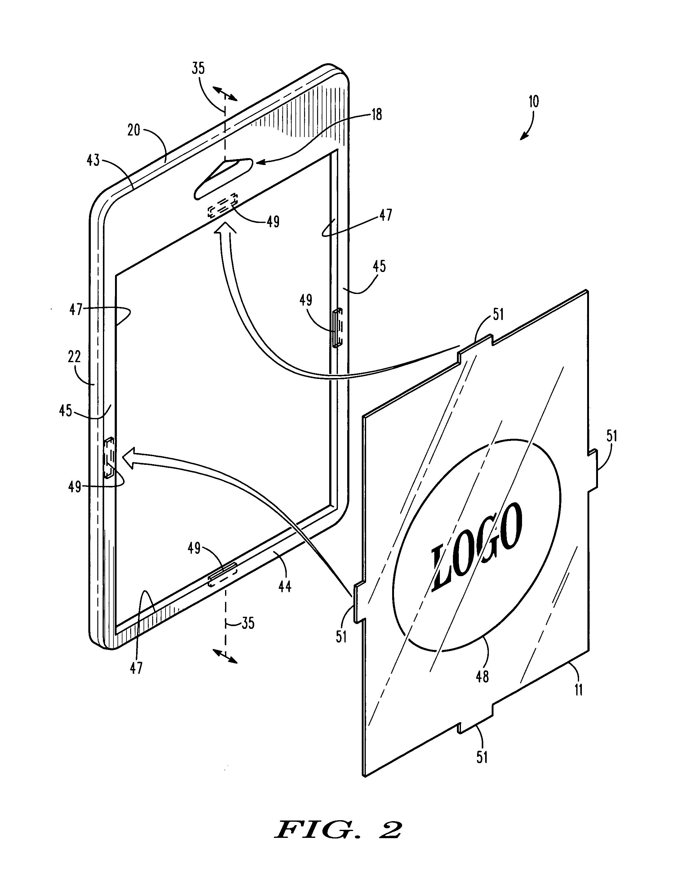
[0059]Referring now to the drawings with more specificity, the present invention essentially provides a neck-hung or neck-worn graphic display device as at reference numerals 10, 10′, and 50, which devices employ certain light guide technology to illuminate a graphic panel as at 11 or 11′ removably and / or interchangenably positioned in anterior adjacency to the anterior illumination surfacing of the graphic display devices 10 / 10′ / 50. Certain developmental similarities and certain developmental distinctions can be traced to, or otherwise seen when compared to certain prior filed U.S. patent applications from which this specification claims a benefit.

[0060]In this last regard, and as noted hereinabove, the present specification(s) claim the benefit of pending U.S. patent application Ser. No. 12 / 821,944 ('944 Application), filed in the United States Patent and Trademark Office on 23 Jun. 2010; pending U.S. patent application Ser. No. 12 / 930,832 ('832 Application), filed in the United S...


PUM

PropertyMeasurementUnit
anglesaaaaaaaaaa
solar energyaaaaaaaaaa
electrical energyaaaaaaaaaa

Abstract

A low profile backlit graphic display device enables a user to display an illuminated graphic hung from the user's neck. The device comprises a housing, a light source assembly, and a number of optical element panels. The housing comprises housing edging, an assembly-receiving cavity, and a coupler-receiving aperture. The housing edging defines a panel-receiving section in anterior adjacency to the assembly-receiving cavity. The light source assembly is receivable in the assembly-receiving cavity. The panels may include a reflector panel, a light guide panel, and an interchangeable graphic panel. The panels are positionable in anterior adjacency to the assembly-receiving cavity within a panel-receiving section. The graphic panel is positionable in anterior adjacency to the light guide panel for illuminating a graphic by way of panel-guided light. A lanyard assembly is attachable to the coupler-receiving aperture and wearable about the neck for enabling the user to display a neck-hung illuminated graphic.

Description

BACKGROUND OF THE INVENTION[0001]This patent application is a continuation-in-part patent application claiming the benefit of pending U.S. patent application Ser. No. 12 / 821,944 ('944 Application), filed in the United States Patent and Trademark Office on 23 Jun. 2010; and pending U.S. patent application Ser. No. 12 / 930,832 ('832 Application), filed in the United States Patent and Trademark Office on 18 Jan. 2011.FIELD OF THE INVENTION[0002]This invention relates generally to a backlit graphic display device. More particularly, the present invention relates to a low profile graphic display device for illuminating interchangeable graphics panels for display in front of the user's chest or torso as hung from the neck by a lanyard assembly.DISCUSSION OF PRIOR ART[0003]Various types of display devices are known in the art for displaying graphics and the like. Several relatively early disclosures describing variously pertinent display devices may be found in U.S. Pat. No. 2,557,383 (Kerw...

Claims


Application Information

Patent Timeline
Patent Type & Authority Applications(United States)
IPC IPC(8): G09F13/04B23P11/00F21V8/00
CPCB60Q1/2673B60Q1/503G09F3/207Y10T29/49826G09F21/02G09F27/007G09F13/005G09F13/22B60Q1/50
Inventor PODD, GEORGE O.
Owner PODD GEORGE O
Learn More