Supercharge Your Innovation With Domain-Expert AI Agents!

Stocks and casing for a rifle

a technology of repeating rifles and stock parts, which is applied in the direction of weapons, breech mechanisms, weapons, etc., can solve the problems of high cost and complex production of connection regions of stock parts, and achieve the effect of avoiding stress concentration and good centering

Active Publication Date: 2011-02-15
BLASER FINANZHLDG
View PDF15 Cites 22 Cited by
  • Summary
  • Abstract
  • Description
  • Claims
  • Application Information

AI Technical Summary

Benefits of technology

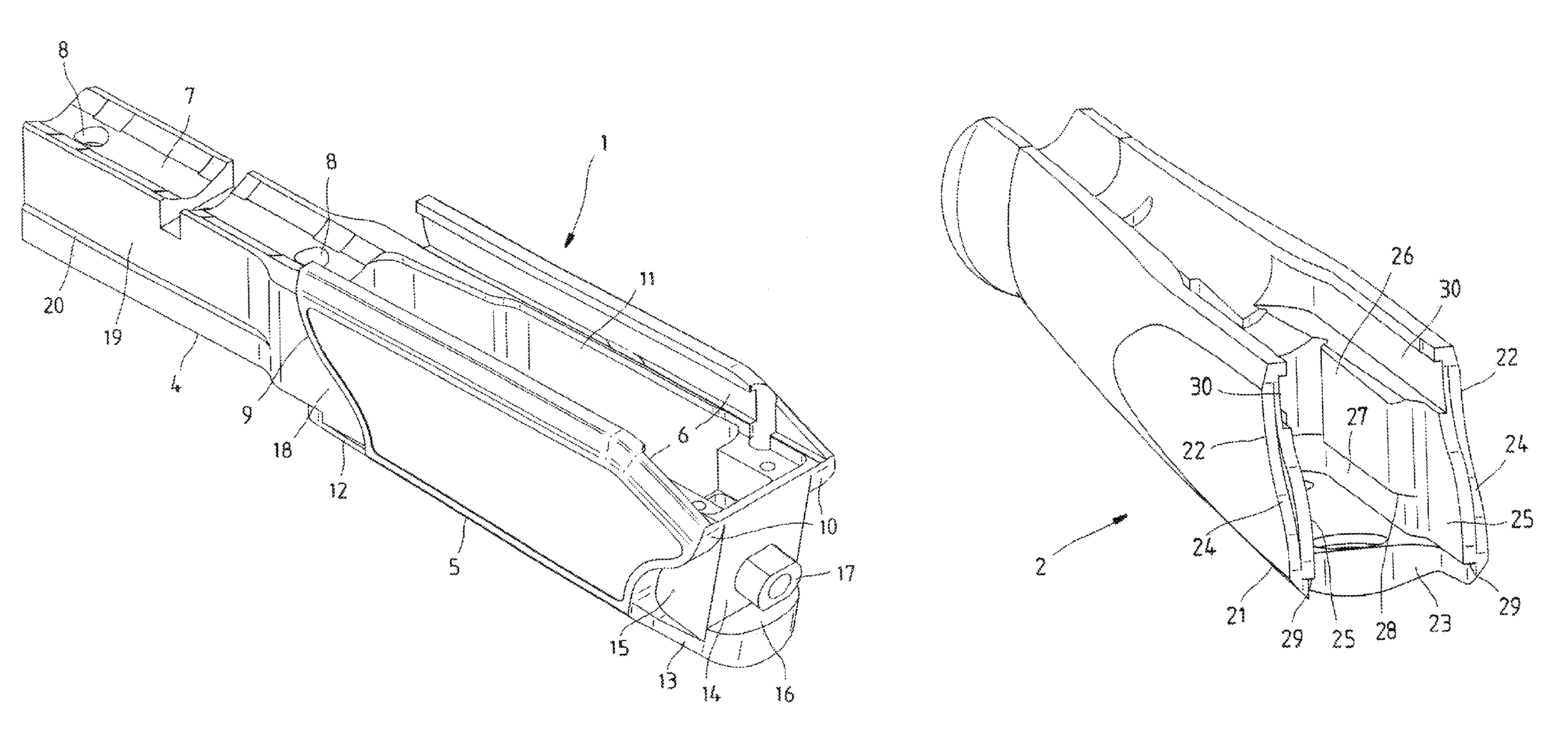
[0006]For the stock according to the invention, a centered and precisely fitting connection to a system casing is achieved through the inward tapering recess on the bottom side of the connection region. The bottom contact surface allows a good support of the stock and can prevent an undesired downward displacement of the stock attached to the system casing. The stock can be mounted easily and with a perfect fit and also features good fitting both in the lateral direction and also upward and downward without high axial triggering forces. Through the special construction of the connection region, a smaller loading appears in the stock in the transverse direction of the fiber, and an especially stable connection secured against displacement between the stock and the system casing is enabled.
[0008]It has proven especially useful if the front closing parts on the system casing and the associated recesses on the front stock feature a tapering angle of 8.2° and the rear closing parts feature a tapering angle of 26.84° with the associated recesses on the rear stock. In this way, good centering is achieved without seizing.
[0009]The closing parts on the system casing and the associated recesses on the stock are preferably rounded at their corners. In this way, a concentration of stresses is avoided.
[0011]The inward tapering recess of the stock is preferably arranged underneath two side cheeks of the connection region. On the insides of the side cheeks there are side faces spaced apart from and parallel to each other for contacting lateral guide faces of the system casing. In this way, good lateral stock fitting is achieved.

Problems solved by technology

Many times this produces the problem that the connection regions of the stock parts must be produced in a relatively complex and expensive way for connecting to the system casing, in order to guarantee a clean stock connection.

Method used


Image

  • Stocks and casing for a rifle
  • Stocks and casing for a rifle
  • Stocks and casing for a rifle

Examples


Embodiment Construction

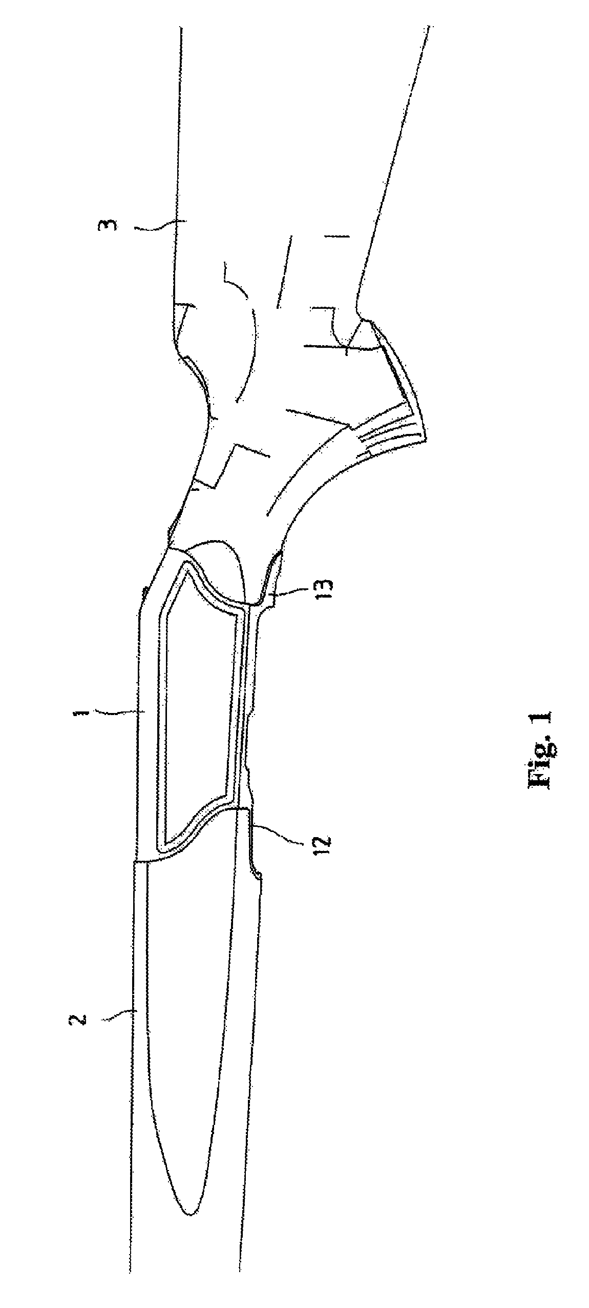
[0021]FIG. 1 schematically shows a part of a repeating rifle with an action housing or system casing 1, a front stock 2, and a rear stock 3 attached to the system casing 1. A not-shown triggering device with a trigger and integrated plug-in magazine can be attached to the bottom side of the system casing 1 in a detachable way.

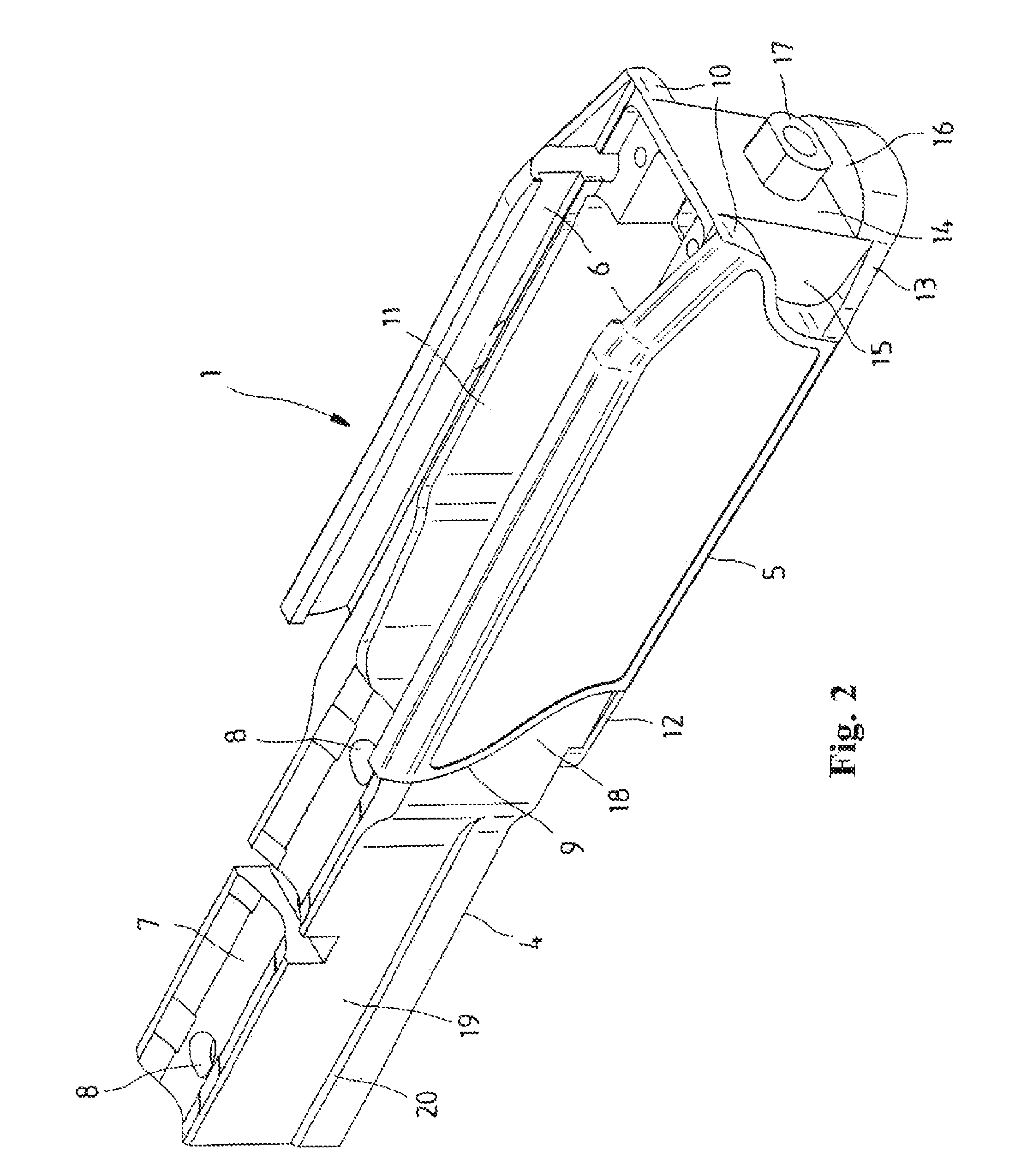
[0022]The system casing 1 shown in different views in FIGS. 2-4 contains, according to FIG. 2, a front contact region 4 and a rear guide region 5 with upper guide grooves 6, in which an action, not shown here, is guided in a displaceable way with a locking chamber in a known way. The front contact region 4 contains an upper contact surface 7 for the rear part of a barrel, not shown, which is attached to the system casing 1 by means of boreholes 8. On the rear guide region 5 of the system casing 1, on the two outer sides there are front and rear S shaped curved contact faces 9 and 10 for corresponding connection surfaces of the front or rear stock. The system ca...


PUM


Abstract

The invention relates to a stock (2; 3) of a repeating rifle with a connection region (21; 22) for connecting the stock (2; 3) to a system casing (1), with the connection region (21; 22) containing curved end connection surfaces (24; 34) for contacting correspondingly curved contact surfaces (9; 10) of the system casing (1) and the connection region (21; 22) having a recess (23; 33) tapering inward on the bottom side and a lower contact surface (28; 38) for contacting an upper support surface (16; 20) of the system casing (1). The invention further relates to a system casing for such a stock and a repeating rifle with such a system casing and stock.

Description

CROSS REFERENCE TO RELATED APPLICATION[0001]This application claims priority under 35 U.S.C. §119 to German Patent Application No. 10 2007 014 899.4 filed Mar. 26, 2007, the entire contents of which are incorporated herein by reference.FIELD OF THE INVENTION[0002]The invention relates to a stock of a repeating rifle, a system casing of a repeating rifle for such a stock, and a repeating rifle with such a system casing and stock.BACKGROUND OF THE INVENTION[0003]Stocks of hand firearms are shaped differently according to the type of weapon. They can be made from one piece or from several sub-pieces. For drop-barrel guns and semiautomatic weapons, the stock is usually divided into a front stock and a rear stock. In a few repeating rifles, the mounting also consists of a front stock and rear stock, which are fixed to a system casing. Many times this produces the problem that the connection regions of the stock parts must be produced in a relatively complex and expensive way for connecti...

Claims


Application Information

Patent Timeline
Patent Type & Authority Patents(United States)
IPC IPC(8): F41C23/00F41C23/16
CPCF41A3/66F41C23/20F41C23/16
Inventor ROTHARMEL, JURGEN
Owner BLASER FINANZHLDG
Features
  • R&D
  • Intellectual Property
  • Life Sciences
  • Materials
  • Tech Scout
  • Unparalleled Data Quality
  • Higher Quality Content
  • 60% Fewer Hallucinations
Learn More