Fuel cutoff valve

a technology of fuel cutoff valve and valve body, which is applied in the direction of functional valve types, containers, underwater equipment, etc., can solve the problems of easy rise and close off of the connection conduit, and achieve the effect of preventing fuel from flowing, high valve closure level, and high level of occluding for

Inactive Publication Date: 2011-02-15
TOYODA GOSEI CO LTD
View PDF13 Cites 12 Cited by
  • Summary
  • Abstract
  • Description
  • Claims
  • Application Information

AI Technical Summary

Benefits of technology

An advantage of some aspects of the invention is provided with a fuel cutoff valve permitting a high valve closure level to be established, while at the same time preventing flow of fuel to the outside when the vehicle turns sharply, as well as designing the valve to resist closure caused by a rising vapor produced by escape of fuel vapors within the fuel tank to the outside.
The fuel cutoff valve in accordance with the present invention is installed in the upper part of the fuel tank, and functions to ensure venting between the fuel tank and the outside, as well as preventing outflow of fuel from the fuel tank by means of rising with the fuel level within the fuel tank and closing off the connection conduit. Moreover, the float has a side communicating hole and an upper vent hole, with the upper vent hole being formed to have greater air flow resistance than the side communicating hole, whereby the float exhibits different behavior with different rates of rise in the fuel level.
Specifically, when vapor flows into the fuel cutoff valve due to a sudden rise in fuel level, the vapor will escape through the side communicating hole of the float so that the float will not easily rise and close off the connection conduit. Consequently, it is possible to establish a high level of shutoff pressure at which the fuel cutoff valve is shut by rising vapor produced when a large volume of fuel vapors flow from the fuel tank to the outside.
Moreover, when the fuel level has risen at a high rate due to swaying of the vehicle, once the side communicating hole is closed off by the fuel in the float chamber, since the flow rate of fuel vapor venting through the upper vent hole is smaller than the flow rate of inflow with the rise in fuel level, the float will now rise rapidly and close off the connection conduit, by utilizing at least some of the buoyant force of the float chamber. Consequently, outflow of fuel to the outside during sharp turning of the vehicle can be prevented.
In a preferred embodiment of the invention, the passage area of the side communicating hole will be designed to allow vapor entering the float chamber to escape into the valve chamber so that the float is not caused to rise; and the passage area of the upper vent hole will be designed so that when the fuel level has risen at a rate slower than a prescribed rate of rise in level and the side communicating hole has become blocked off by fuel, vapor entering the float chamber will escape into the valve chamber as the float chamber fills with fuel, causing the float to rise; whereas when the fuel level has risen at a rate faster than the prescribed rate of rise in level and the side communicating hole has become blocked off by fuel, the float is caused to rise through the increasing buoyant force of the float utilizing at least some of the float chamber as buoyant force. The arrangement for establishing the air flow resistance of the upper vent hole and the side communicating hole can involve employing various different shapes and passage area for the passages, but can be achieved more simply by varying the passage area.
The seat portion may be integrally formed with the float, or constituted as a separate element. Specifically, in a preferred embodiment of the invention, the float mechanism may comprise a rubber seat member installed on the upper part of the float, with the seat portion being formed on the upper face of the seat member. By means of this arrangement, even when the fuel cutoff valve is submerged, the seat member will flex when seated in the seal portion of the connection conduit, and can exhibit high sealing ability.

Problems solved by technology

Specifically, when vapor flows into the fuel cutoff valve due to a sudden rise in fuel level, the vapor will escape through the side communicating hole of the float so that the float will not easily rise and close off the connection conduit.

Method used


Image

  • Fuel cutoff valve
  • Fuel cutoff valve
  • Fuel cutoff valve

Examples


Embodiment Construction

(1) General Arrangement of Fuel Cutoff Valve 10

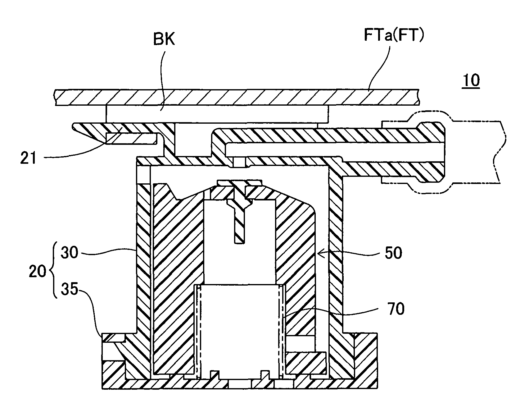
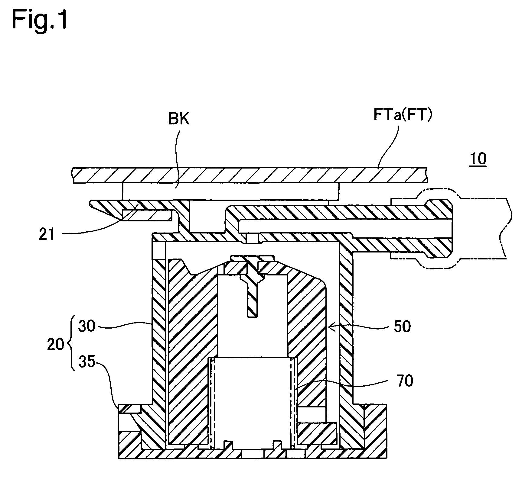
FIG. 1 is a sectional view showing a fuel cutoff valve 10 attached to the upper part of a fuel tank FT of an automobile in one embodiment of the invention. The fuel cutoff valve 10 is of so-called in-tank type installed inside the fuel tank FT. The fuel cutoff valve 10 functions as a valve for preventing fuel from flowing to the outside in the event of a rise in fuel level within the fuel tank FT when the vehicle inclines or turns rapidly for example. The fuel cutoff valve 10 comprises as its principal parts a casing 20, a float mechanism 50, and a spring 70. A valve mounting portion 21 is integrally formed in the upper part of the casing 20 and is attached to the inside of the fuel tank FT via a bracket BK which is welded to the lower face of a tank upper wall FTa of the fuel tank FT.

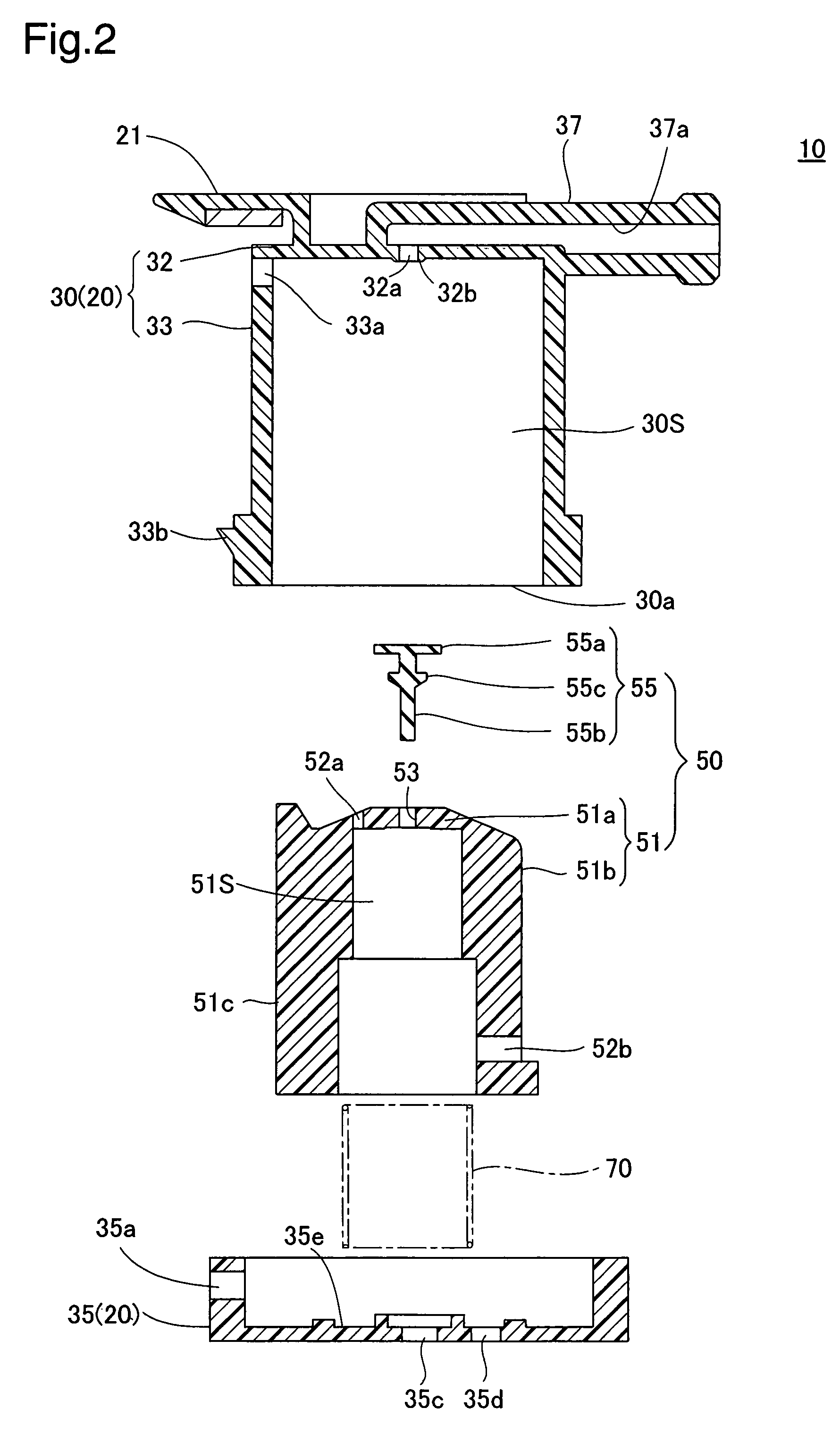
(2) Arrangement of Fuel Cutoff Valve 10 Parts

FIG. 2 is an exploded sectional view of the fuel cutoff valve. In FIG. 2, the casing 20 comprises a casing bo...


PUM


Abstract

A fuel cutoff valve comprises a casing and a float mechanism having a float and a seat portion. An upper vent hole is formed in the upper wall portion of the float, and a side portion communication hole is formed in the side wall portion. The passage area of the side portion communication hole is set so as to allow a large volume of vapors entering the float chamber to escape into the valve chamber. The passage area of the upper vent hole is set so that vapor entering the float chamber when the vehicle inclines escapes into the valve chamber, and the float chamber fills with fuel lifting the float, whereas when the vehicle turns sharply, the float is lifted without the float chamber filling with fuel.

Description

This application claims the benefit of and priority from Japanese Application No. 2006-37408 filed Feb. 15, 2006, the content of which is incorporated herein by reference.BACKGROUND OF THE INVENTION1. Field of the InventionThe present invention relates to a fuel cutoff valve that is mounted on an upper wall of a fuel tank, and opens and closes a connection conduit to connect the fuel tank and outside.2. Description of the Related ArtThe upper part of a fuel tank is typically equipped with a full tank regulator valve connected to a canister, discovered in Japanese Patent No. 30648924, or with a fuel cutoff valve (rollover valve). The valves, by opening and closing at a prescribed fuel level, ensures venting of the fuel tank to the outside, as well as preventing fuel from flowing to the outside. A rollover valve is designed to shutoff fuel to the outside at a fuel level above the full tank level in order to ensure venting when the vehicle leans or slaloms during driving.In line with i...

Claims


Application Information

Patent Timeline
Patent Type & Authority Patents(United States)
IPC IPC(8): F16K24/04
CPCB60K15/03519F16K17/36F16K24/042Y10T137/0874Y10T137/0826Y10T137/3099
Inventor MIYOSHI, KEIJIAOKI, TOMOHIDEKAGAMIUCHI, SHINOBU
Owner TOYODA GOSEI CO LTD
Why Eureka
Try Eureka