

Transport container system with sidewall attachment elements for increasing the transport capacity
a technology of sidewall attachment elements and transport containers, which is applied in the field of transport container systems, can solve the problems of difficult optimal filling of transport containers, inability to adjust the volumetric capacity of transport containers, and increased production costs, so as to achieve stable and reliable stacking, prevent the shifting of crates, and easy stacking
- Summary
- Abstract
- Description
- Claims
- Application Information
AI Technical Summary
Benefits of technology
Problems solved by technology
Method used
Image

Examples
Embodiment Construction
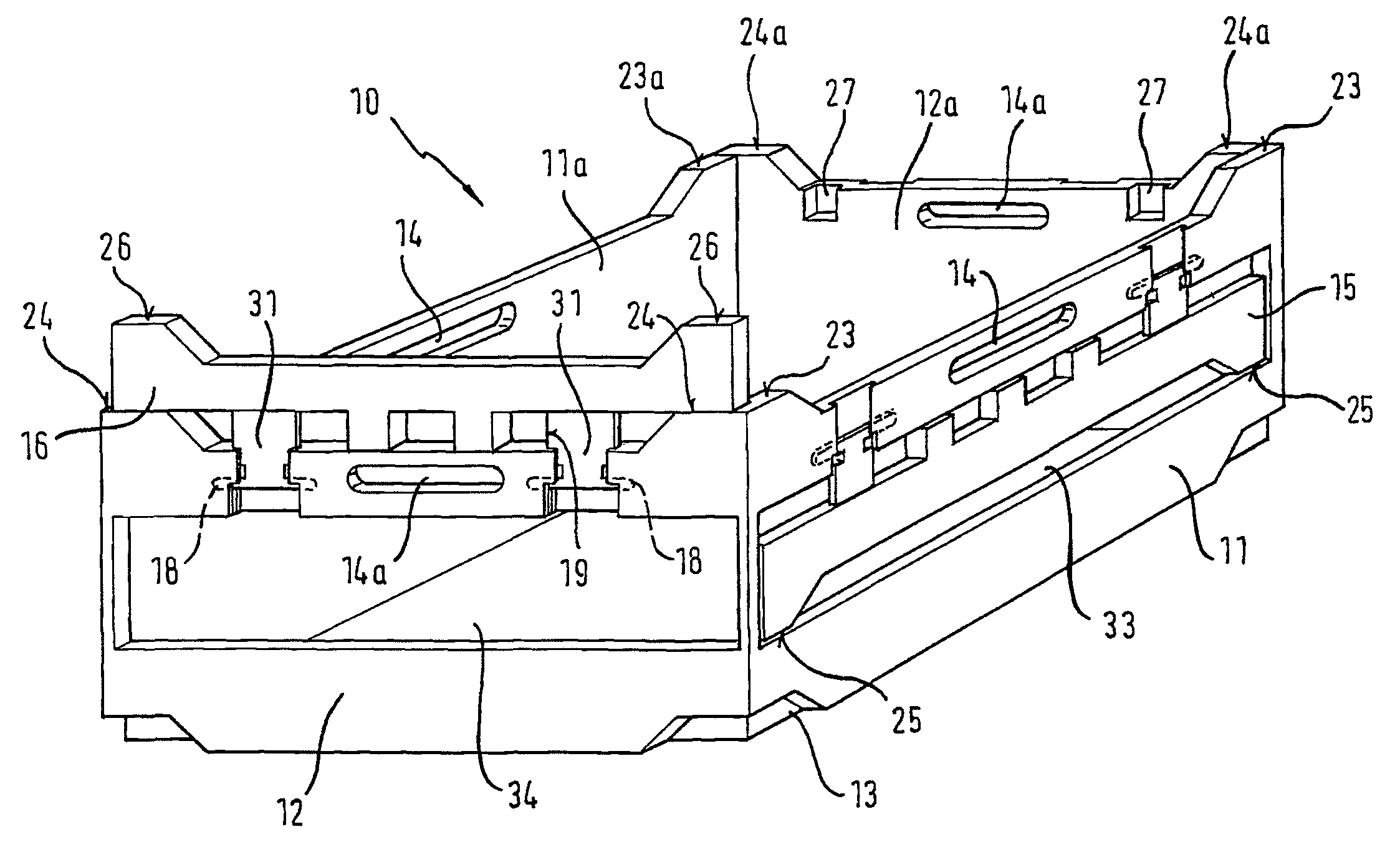
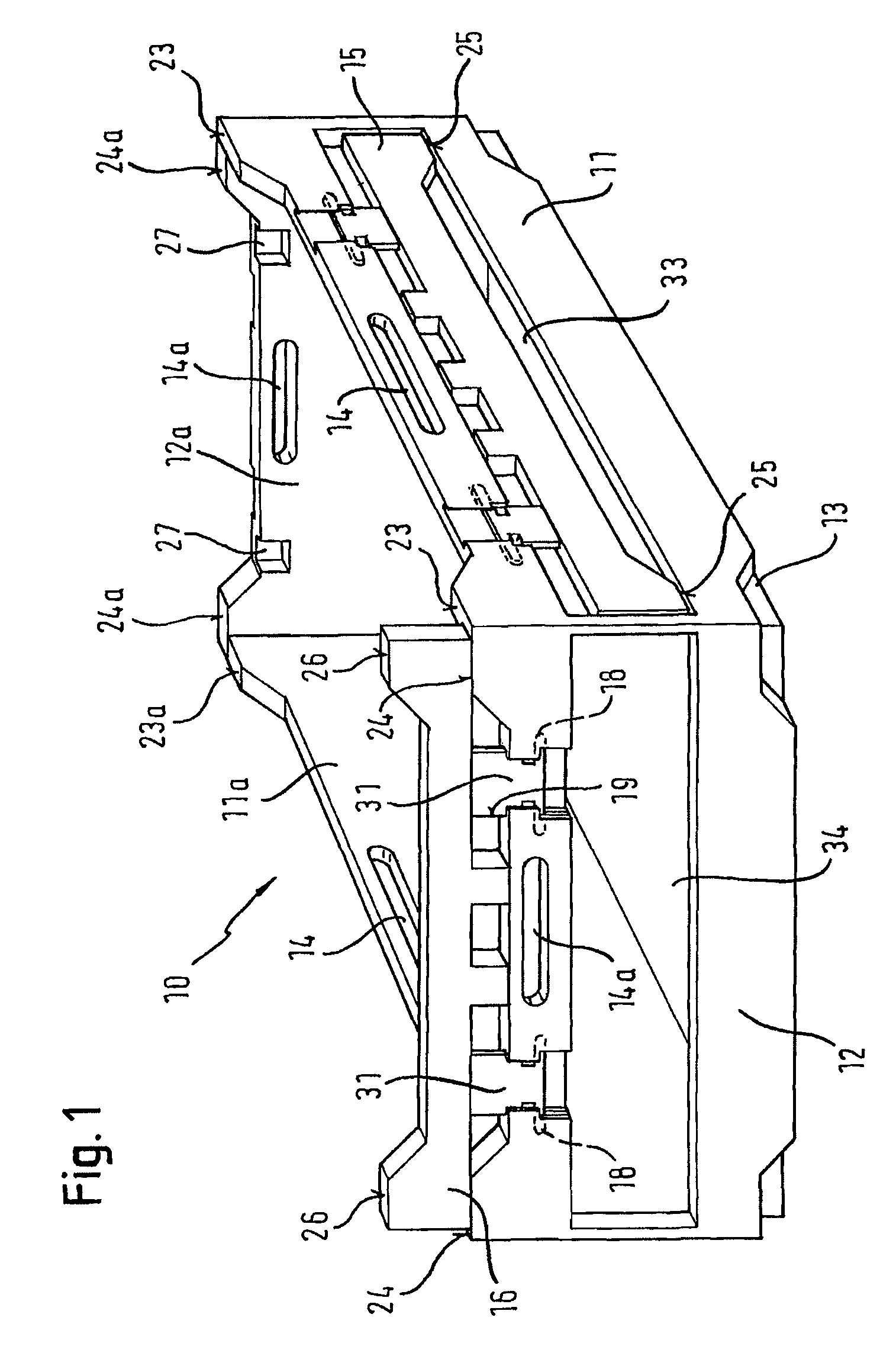
FIG. 1 is a perspective view of one possible embodiment of a transport container 10 according to the invention. The transport container 10 of FIG. 1 comprises a collapsible crate 10 having a bottom element 13 and attachment elements 15, 15a, 16, 16a which are undetachably mounted on side wall elements 11, 11a, 12, 12a. As can be seen in FIG. 1, the attachment element 15 is integrated into a recess 33 and is substantially flush therewith in the direction of thickness, i.e. if at all, the attachment element 15 will only protrude slightly over the side wall element 11 in the direction of its thickness. Just as the attachment element 15 is accommodated in the side wall 11 of FIG. 1, the attachment elements 15a, 16 and 16a can also be accommodated in their respective side walls 11a, 12 and 12a.
With the attachment elements 15, 15a, 16 and 16a folded down and the side wall elements 11, 11a, 12 and 12a folded up, the upper bearing surfaces 23, 23a, 24 and 24a of the side wall elements 15, ...
PUM
 Abstract
Description
Claims
Application Information