Injection valve

a technology of injection valve and injection chamber, which is applied in the direction of fuel injection apparatus, engine components, feed systems, etc., can solve the problems of expensive hermetic sealing and achieve the effect of simple hydraulic bearing

Inactive Publication Date: 2011-02-15
SIEMENS AG
View PDF48 Cites 40 Cited by
  • Summary
  • Abstract
  • Description
  • Claims
  • Application Information

AI Technical Summary

Benefits of technology

[0006]The object of the present invention is to provide an efficient injection valve with a simple hydraulic bearing.
[0009]There is implemented an injector principle which obviates the need for an additional operating medium for the hydraulic bearing. The fuel fills via at least one annular gap the valve's hydraulic chamber which ensures length compensation.
[0010]The fuel-pressurized hydraulic chamber is advantageously of very rigid construction in order to be able to absorb very high compressive and tensile forces for short periods, as is required for rapid opening and closing of the valve. The injection valve can therefore close approximately 5-10 times as quickly as in the case of resetting by a return spring alone according to the prior art, while at the same time preventing the losses in the valve needle stroke caused by the disadvantageous extension of the valve needle because of a high restoring force acting through the return spring.
[0012]By means of appropriate routing of the fuel ducts, the fuel flows past the drive unit and, for example, the multilayer actuator and cools the piezoceramics. A further advantage therefore consists in the improved temperature characteristics of the injector. Direct injection into the combustion chamber subjects the injector to high temperatures. Moreover, modern injection concepts provide for multiple injections. The trend is toward continuous injection rate forming. Concepts involving 5 injections per cycle are already under discussion. This would produce additional waste heat. Injector cooling is therefore advantageous, even if no temperature problem has yet arisen with injectors according to the prior art using silicone oil as operating medium for the hydraulic bearing.

Problems solved by technology

However, this necessitates expensive hermetic sealing of the operating medium, e.g. silicone oil, against the pressurized fuel, the seal frequently being implemented by a metal bellows.

Method used


Image

  • Injection valve
  • Injection valve
  • Injection valve

Examples


Embodiment Construction

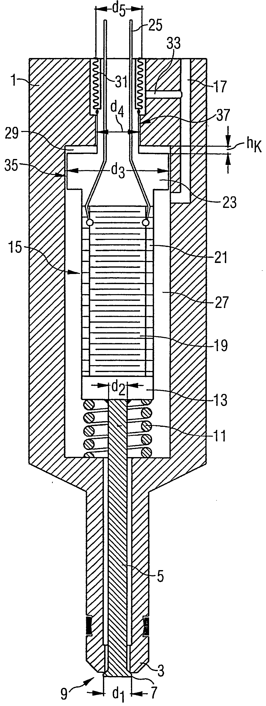
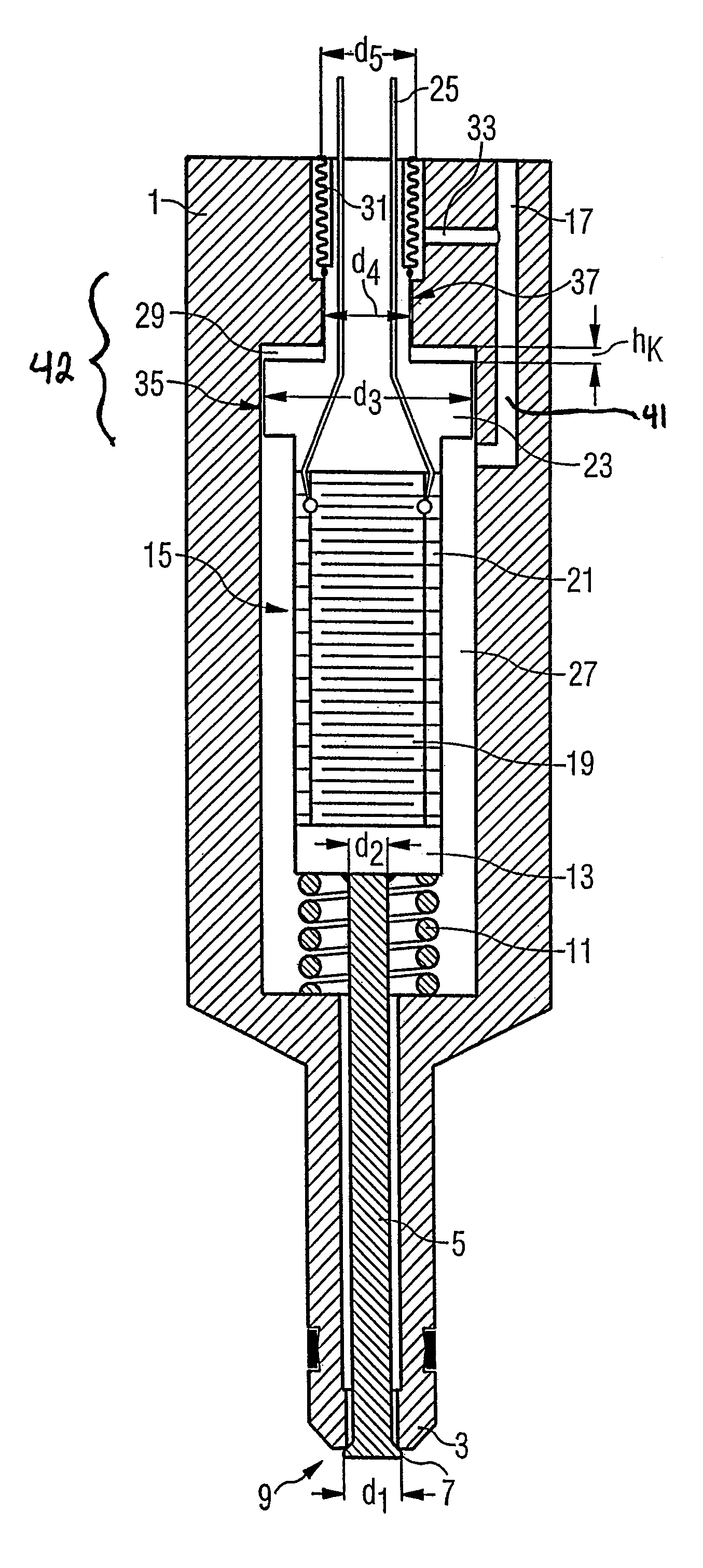
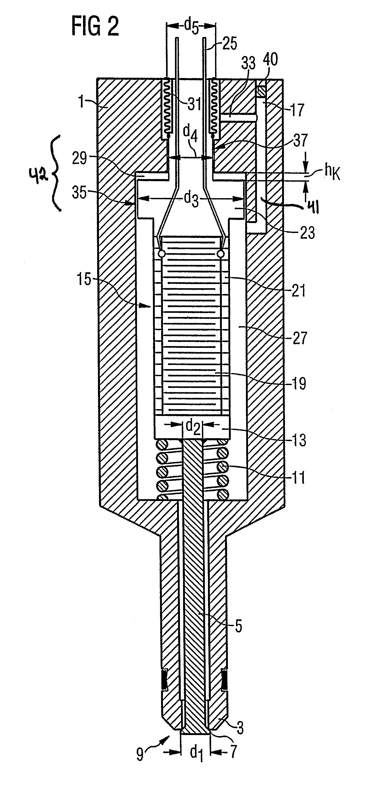
[0016]A high-pressure injector or the injection valve has a valve seat 3 in an injector housing 1. One diameter of the sealing line d1 is typically 3-5 mm for a fuel-injection valve. In the basic state the valve seat 3 is held closed by means of a valve disk 7 connected to the lower end section of a valve needle 5 (diameter d2), said valve needle 5 being disposed in a valve housing 1. The closed basic state of an injection nozzle 9 formed by the valve seat 3 and the valve disk 7 at the end of the housing 1 is ensured by a tensioned compression spring 11 with a typical spring force (Fs) of approximately 150 N. The compression spring is mounted between a base plate 13 of a drive unit 15 and a section of the inner wall of the valve housing 1. The valve needle 5 is rigidly connected, e.g. welded, to the base plate 13. The fuel is supplied to an inner chamber of the valve housing 1 through a duct bore 17 provided in the injector housing 1. In the upper section of the injector housing 1 t...


PUM


Abstract

An injection valve for injecting fuel comprises a valve housing (1) inside of which a drive unit (15) controls the movement of a valve needle (5) that is pretensioned by a spring (11). The injection valve also comprises a main chamber (27), which is provided inside the valve housing, is filled with fuel and accommodates the valve needle (5), and comprises a hydraulic bearing for the drive unit (15). The hydraulic bearing has a hydraulic chamber (29) that is connected to the main chamber (27), whereby fuel serves as the operating substance of the hydraulic bearing.

Description

CROSS REFERENCE TO RELATED APPLICATION[0001]This application is a continuation of copending International Application No. PCT / DE03 / 01062 filed Apr. 1, 2003 which designates the United States, and claims priority to German application no. 102 14 931.3 filed Apr. 4, 2002.TECHNICAL FIELD OF THE INVENTION[0002]The present invention relates to an injection valve.DESCRIPTION OF THE RELATED ART[0003]An injection valve of this kind is known from DE 198 54 508, the valve needle being designed to open outward, and the valve needle and housing having axially cooperating pressure surfaces implemented in such a way that, if the fluid pressure changes, the same axial variation in length occurs on the valve needle and on the valve housing. It is additionally possible to set the surfaces on the valve needle in such a way that the pressure of the fluid causes no force to be exerted on the return spring or valve seat, the drive chamber in which the drive unit is disposed and the fluid chamber in whic...

Claims


Application Information

Patent Timeline
Patent Type & Authority Patents(United States)
IPC IPC(8): B05B1/08F02M51/06F02M61/08F02M61/16F02M61/20
CPCF02M51/0603F02M61/08F02M61/167
Inventor BACHMAIER, GEORGFISCHER, BERNHARDGOTTLIEB, BERNHARDKAPPEL, ANDREASMEIXNER, HANSULIVIERI, ENRICO
Owner SIEMENS AG
Why Eureka
Try Eureka