Headrest device in a chair

a headrest and chair technology, applied in the field of headrest devices in chairs, can solve the problems of insufficient support strength, unstable side, and insufficient headrest support, and achieve the effects of high strength, easy assembly, and easy movement up and down

Inactive Publication Date: 2011-02-15
OKAMURA CORP
View PDF13 Cites 79 Cited by
  • Summary
  • Abstract
  • Description
  • Claims
  • Application Information

AI Technical Summary

Benefits of technology

[0008]In view of the disadvantages, it is an object of the present invention to provide a headrest device in which a headrest is stably supported on a headrest frame to move up and down, an elevating member for the headrest being easily assembled to the headrest frame.
[0009]It is another object of the invention to provide a headrest device in which the headrest is easily movable up and down, an elevating member for the headrest being made as small as possible.
[0010]It is further object of the invention to provide a headrest device in which a headrest frame has high strength to allow the headrest to be supported stably.

Problems solved by technology

The headrest is not so strongly supported and each side is unstable.
But in both of the headrest devices, when the headrest moves up away from the backrest support frame, a support strength is not sufficient and the headrest and support therefore+ are likely to be unstable.
For mounting the elevating member, the side rods of the headrest frame have to be elastically changed in shape outward and sideward by a strong force to increase a gap between opposing surfaces to make mounting troublesome.
It would be very difficult to move the headrest up and down easily.
Also the engagement projection strongly rubs against the groove to cause wear and loosening.
So appearance becomes poor and it would be very difficult to design the elevating member itself and the headrest device freely.

Method used


Image

  • Headrest device in a chair
  • Headrest device in a chair
  • Headrest device in a chair

Examples


Embodiment Construction

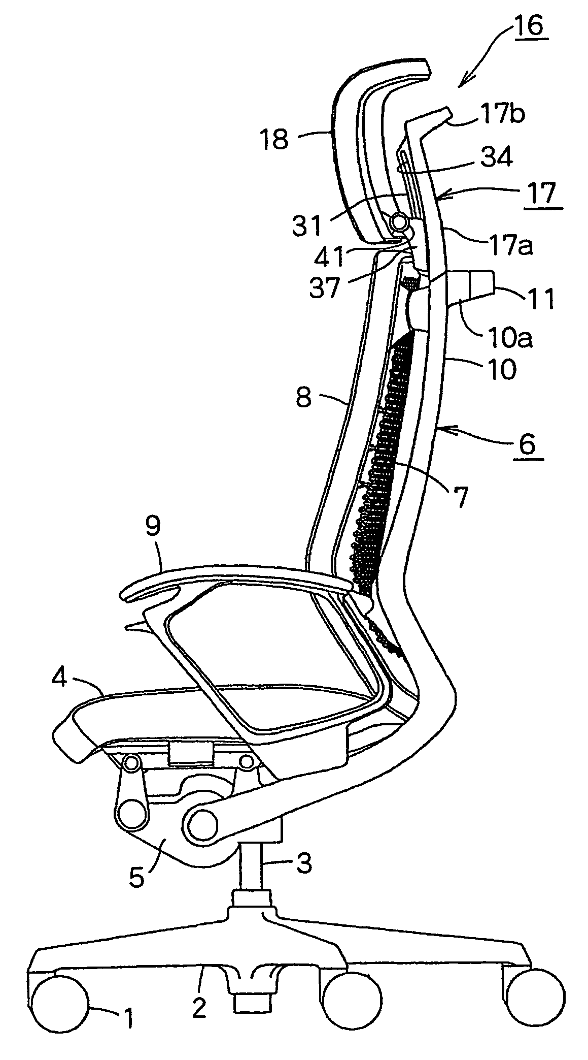
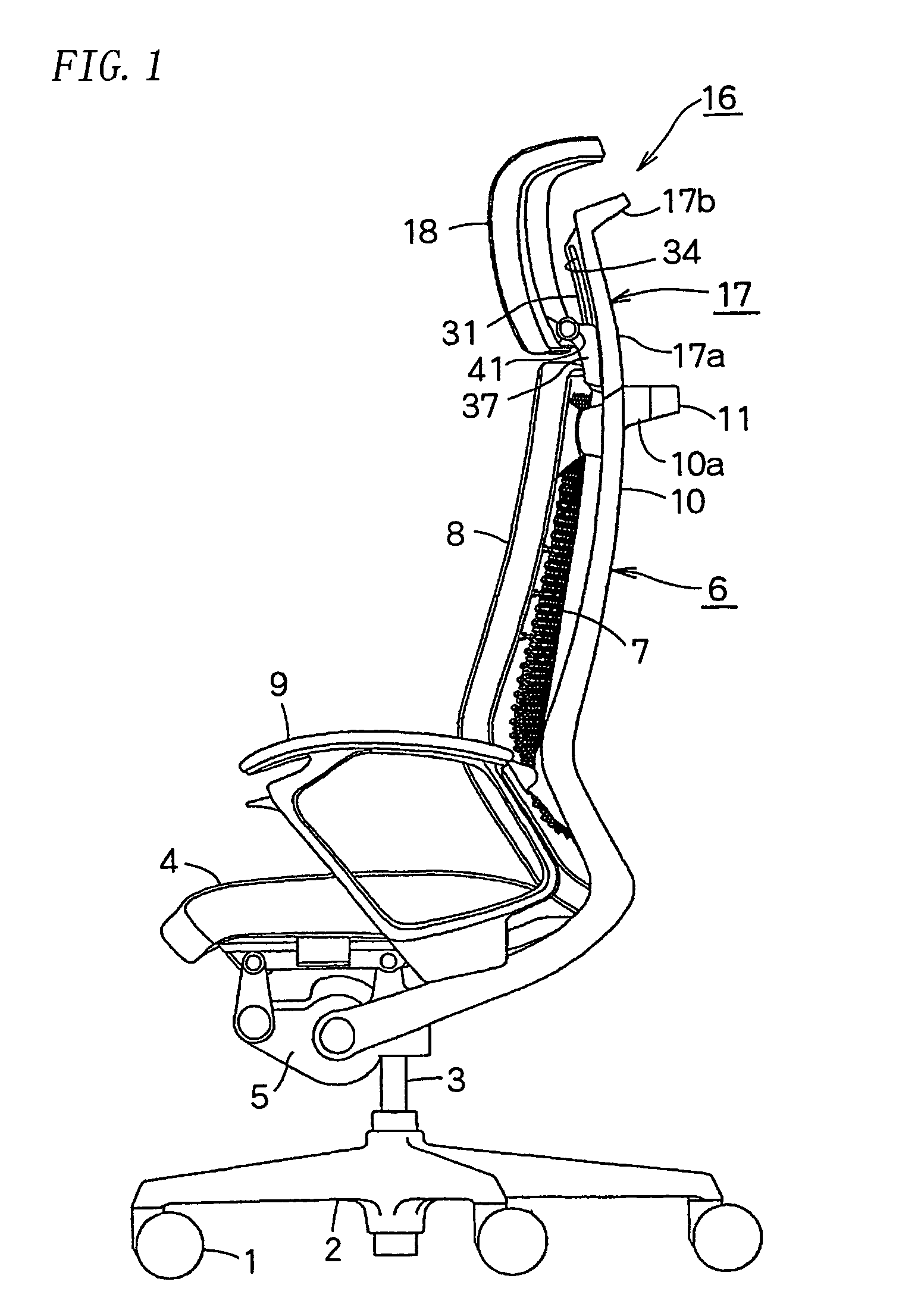
[0021]FIG. 1 is a side elevational view of a chair comprising a headrest according to the present invention and FIG. 2 is a rear elevational view thereof. The chair comprises a leg 2 with casters 1; a post 3 standing on the middle of the leg 2; a support base 5 supporting a seat 4 at the upper end; a backrest support frame 6 which is pivotally connected to the support base 5 and stands at the rear end of the seat 4; and a pair of armrests 9,9 at the lower parts of the backrest support frame 6.

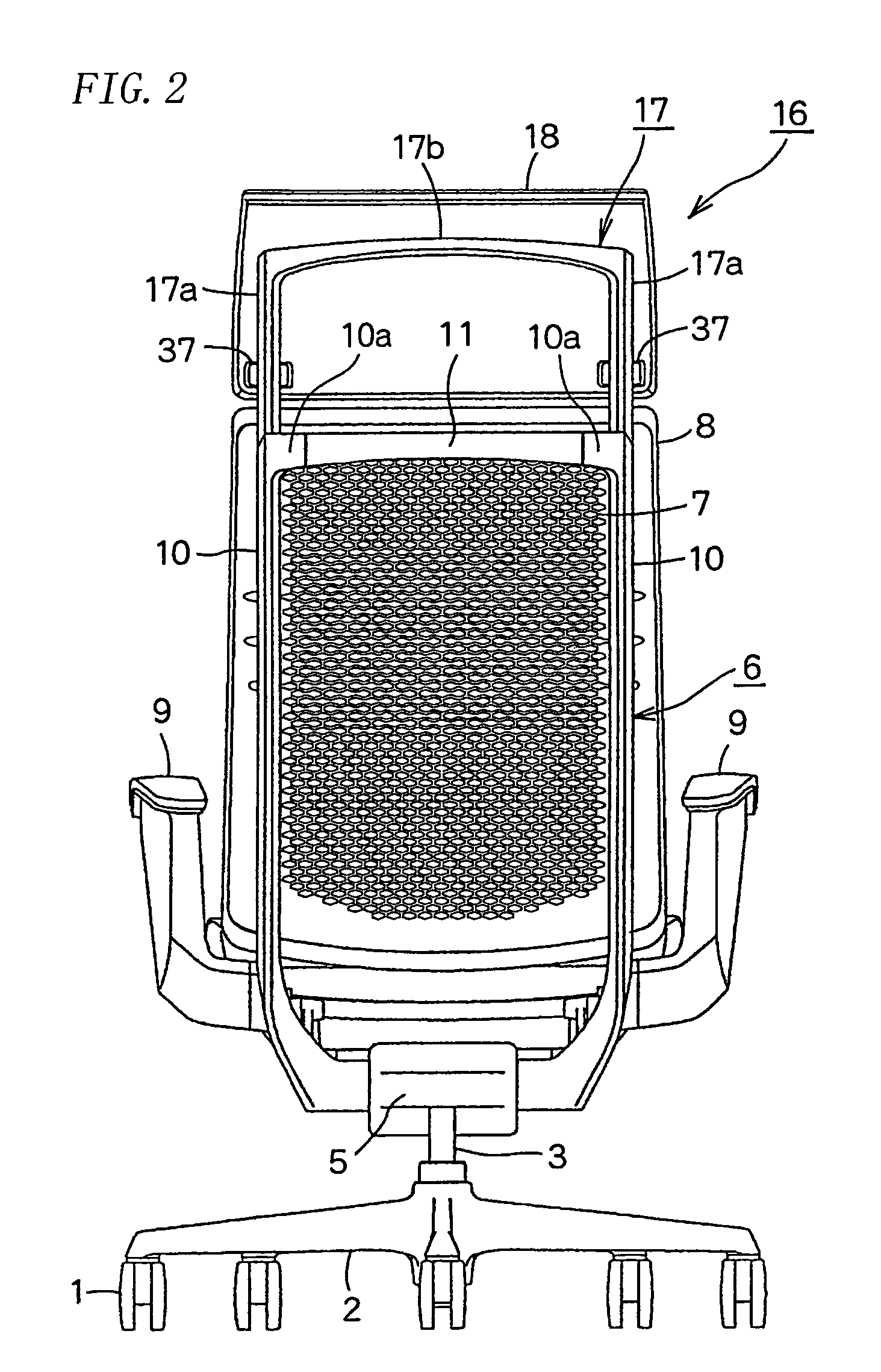
[0022]A mesh backrest plate 7 of the backrest 8 is mounted on the front surface of the backrest support frame 6.

[0023]In FIG. 3, the inverse-U-like backrest support frame 6 comprises a pair of side portions 10,10 molded of Al alloy; and a lateral portion 11 molded of Al alloy.

[0024]Connecting portions 10a,10a project at the upper ends of the side portions 10 and are continuously formed with the lateral portion 11.

[0025]At each end of the lateral portion 11, a groove 12 is formed and a bolt 13 i...


PUM


Abstract

A headrest device of a chair in which a headrest can be stably supported by a headrest frame and the operation for mounting a vertically moving member of the headrest is easily performed. Guide grooves are formed in the side faces of guide rails at the front faces of the right and left side-rods of the headrest frame. The right and left guide rails are so held by a pair of right and left lifting brackets, which are provided on the rear surface of the headrest and are formed in rearward U-shape when viewed from above, as to be capable of sliding vertically from the front. Projected guide pieces formed to be projected on the inner surfaces of both vertically moving brackets and facing in the vertical direction are slidably fitted into the guide grooves of the right and left guide rails.

Description

TECHNICAL FIELD[0001]The present invention relates to a headrest device in a chair, comprising a headrest supported by a headrest frame extending upward from a backrest support frame to move up and down.BACKGROUND OF THE INVENTION[0002]Such a headrest device is disclosed in JP2001-314268A, JP2003-79474A and JP2004-202062A.[0003]JP2001-314268A discloses a headrest device in which a headrest is mounted in the middle of an upper lateral rod of a backrest support frame. The headrest is not so strongly supported and each side is unstable.[0004]JP2003-79474A discloses a headrest device in which a headrest is mounted to a headrest rod projecting from the backrest, and JP2004-202062A discloses a headrest device in which a headrest frame is supported in the middle of a backrest support frame to move up and down, a headrest being mounted in the middle at the upper end of the headrest frame. But in both of the headrest devices, when the headrest moves up away from the backrest support frame, a...

Claims


Application Information

Patent Timeline
Patent Type & Authority Patents(United States)
IPC IPC(8): A47C7/36
CPCA47C1/036A47C7/38
Inventor ODA, YOICHIRO
Owner OKAMURA CORP
Why Eureka
Try Eureka