Surgical cutting accessory with encapsulated RFID chip

a technology of encapsulated rfid and cutting accessories, which is applied in the field of surgical cutting accessories with encapsulated rfid chips, can solve the problems of increasing the overall size and weight of the handpi

Active Publication Date: 2011-02-15
STRYKER CORP
View PDF45 Cites 70 Cited by
  • Summary
  • Abstract
  • Description
  • Claims
  • Application Information

AI Technical Summary

Problems solved by technology

This handpiece lengthening can increase the overall size and weight of the handpiece.

Method used


Image

  • Surgical cutting accessory with encapsulated RFID chip
  • Surgical cutting accessory with encapsulated RFID chip
  • Surgical cutting accessory with encapsulated RFID chip

Examples


Embodiment Construction

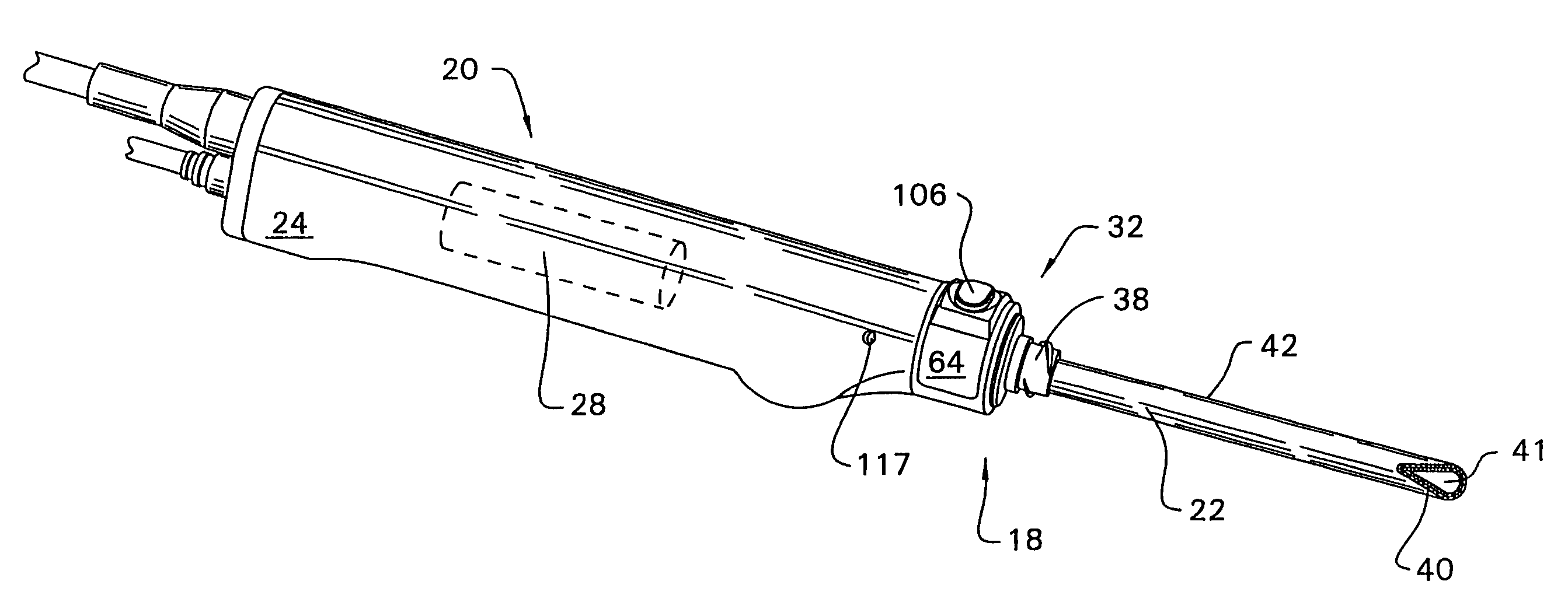
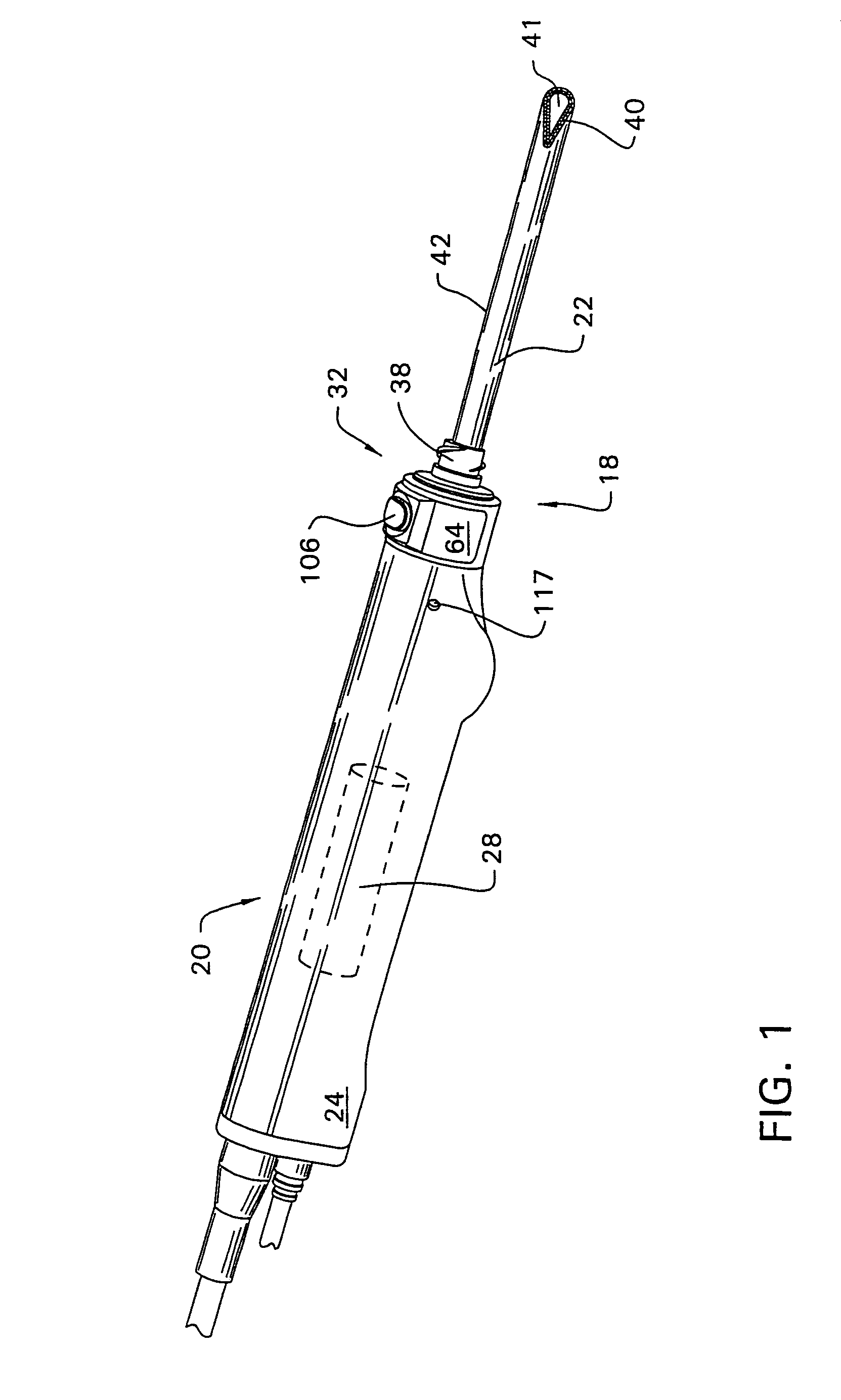
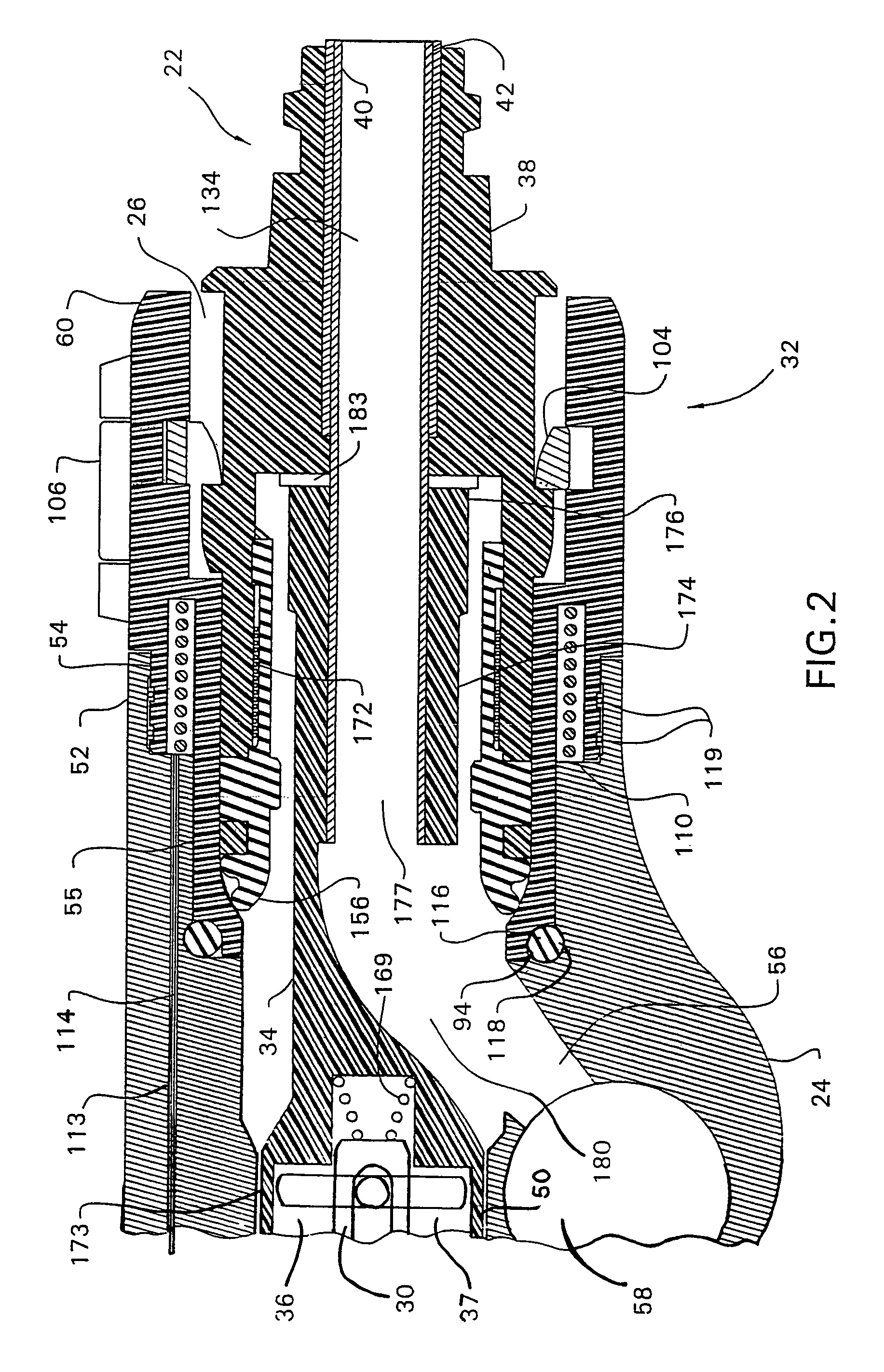
[0030]The surgical tool system 18 of this invention, as seen in FIGS. 1 and 2, includes an endoscopic handpiece 20, sometimes called a surgical tool. A complementary cutting accessory 22 is attached to the handpiece 20. The handpiece 20 includes a generally cylindrical, elongated housing 24. The distal end of the housing 24 is formed with a bore 26 for receiving the proximal end of the cutting accessory 22. (Throughout this document, “distal” is understood to be away from the face of the surgeon holding the handpiece 20; “proximal” is understood to mean towards the face of the surgeon.) A motor 28, depicted in phantom, is disposed inside the housing 24. A rotating output shaft 30, which is connected to the motor 28 for actuation by the motor, is disposed inside bore 26. A coupling assembly 32 is mounted to the front end of the housing 24 for removably holding the cutting accessory 22 to the handpiece 20.

[0031]The cutting accessory 22 includes a drive hub 34 that releasably engages t...


PUM


Abstract

A cutting accessory for use with a powered surgical tool. The accessory includes a drive shaft to which an outer hub is attached. Internal to the outer hub is a self-contained transponder formed from an RFID chip and a coil of electrical conductor embedded within a solid substrate or encapsulated within a plastic enclosure. The transponder wirelessly communicates one or more pieces of information concerning the identity and operation of the accessory to the surgical tool when the accessory is attached to the surgical tool.

Description

RELATIONSHIP TO EARLIER-FILED APPLICATIONS[0001]This application is a continuation-in-part of U.S. patent application Ser. No. 10 / 319,300, filed Dec. 13, 2002, which issued as U.S. Pat. No. 7,237,990 and is a continuation-in-part of U.S. patent application Ser. No. 10 / 214,937, filed Aug. 8, 2002 now abandoned. The contents of the above-listed priority applications are incorporated herein by reference.FIELD OF THE INVENTION[0002]This invention is related generally to a surgical cutting accessory for use with a powered surgical tool system and, more particularly, to a surgical cutting accessory with an RFID chip that contains data regarding the operation of the cutting accessory.BACKGROUND OF THE INVENTION[0003]Endoscopic surgical procedures are routinely performed in order to accomplish various surgical tasks. In an endoscopic surgical procedure, small incisions, called portals, are made in the patient. An endoscope, which is a device that allows medical personnel to view the surgica...

Claims


Application Information

Patent Timeline
Patent Type & Authority Patents(United States)
IPC IPC(8): A61B17/32A61B17/00A61B19/00
CPCA61B17/32002A61B2017/00477A61B2017/00482A61B2019/448A61B90/98
Inventor DENG, WENJIEKAUKER, BARRY J.
Owner STRYKER CORP
Why Eureka
Try Eureka