Lead frame, method of making the same and light receiving/emitting device

a technology of lead frame and light emitting device, which is applied in the field of lead frame, can solve the problems of significantly reducing the reflectivity of silver coating, and achieve the effect of suppressing the deterioration of the characteristics of silver coating

Active Publication Date: 2011-02-15
STANLEY ELECTRIC CO LTD +1
View PDF18 Cites 7 Cited by
  • Summary
  • Abstract
  • Description
  • Claims
  • Application Information

AI Technical Summary

Benefits of technology

[0007]It is an object of the invention to provide a lead frame that deterioration in characteristics thereof can be suppressed even after long-term use, a method of making the lead frame and a light receiving / emitting device using the lead frame.
[0014]the characteristic sustaining layer prevents a decrease in the reflectivity of the reflection layer and transmits light reflected by the reflection layer.

Problems solved by technology

However, when the silver coating of the lead frame in Japanese patent No. 3940124 is exposed outside before mounting the light emitting device, a problem may arise that the reflectivity of the silver lowers due to sulfuration and / or oxidation.
Furthermore, a problem may arise that, even when the inside of the enclosure is filled by a sealing resin after mounting the light-emitting device, the silver coating is sulfurated and / or oxidized by sulfur and / or oxygen penetrated through the resin due to long-term use (e.g., about one year use), so that the reflectivity of the silver coating significantly lowers.

Method used


Image

  • Lead frame, method of making the same and light receiving/emitting device
  • Lead frame, method of making the same and light receiving/emitting device
  • Lead frame, method of making the same and light receiving/emitting device

Examples


first embodiment

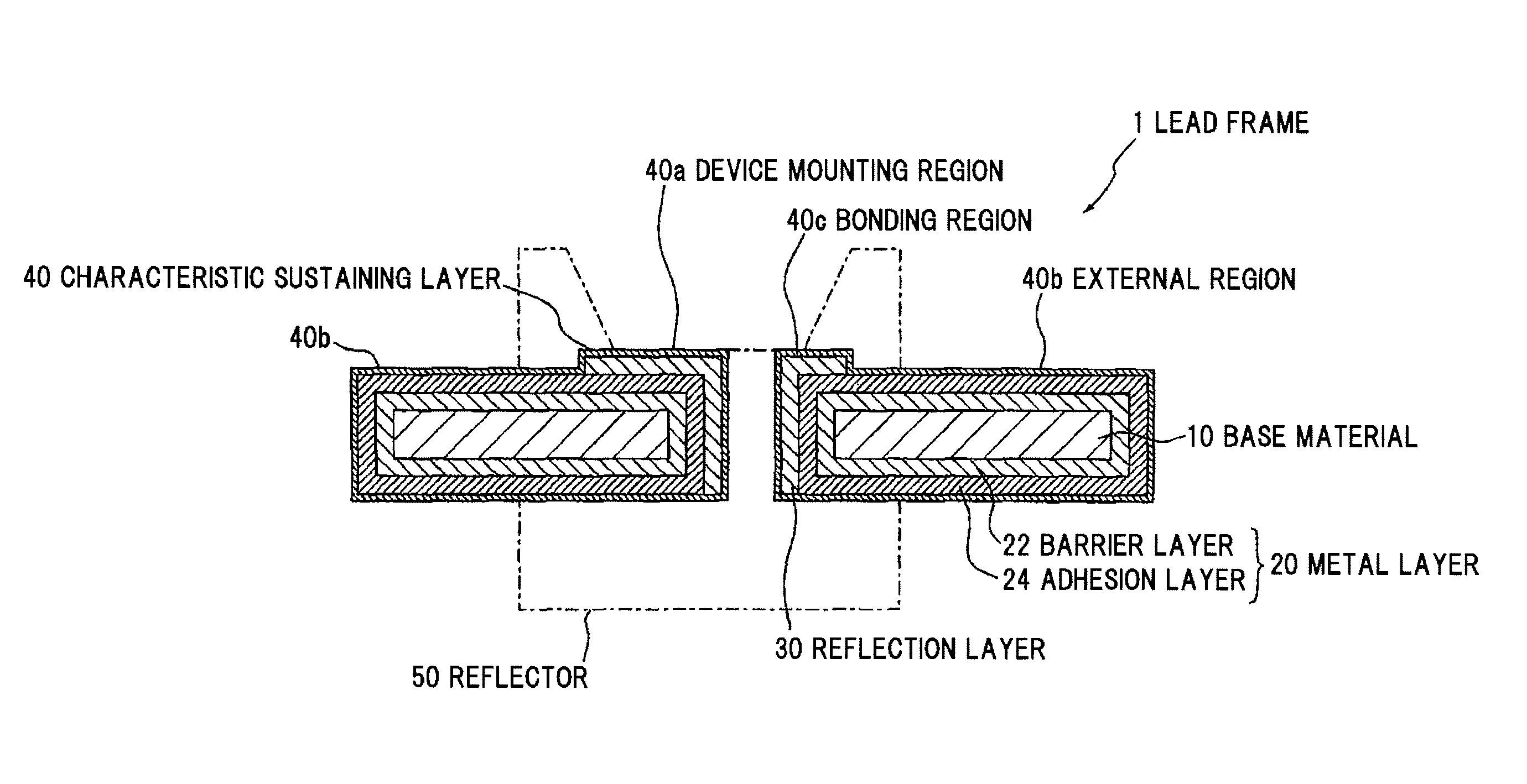
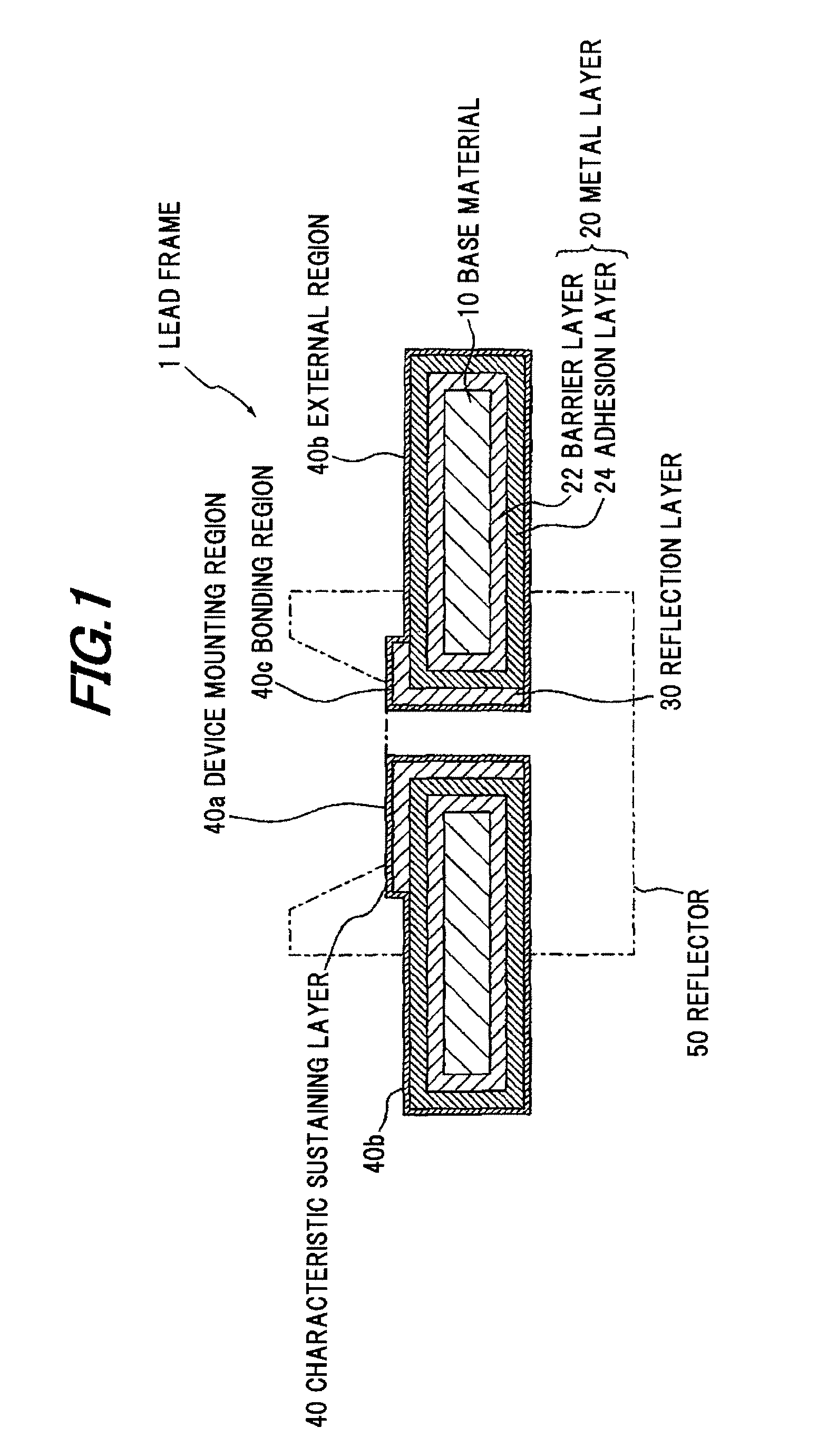
[0052]FIG. 1 is a cross sectional view showing a lead frame in a first embodiment of the invention.

[0053]Construction of Lead Frame 1

[0054]A lead frame 1 in the first embodiment of the invention is composed of a base material 10 formed of a material for a lead frame, a metal layer 20 formed on the surface of the base material 10, a reflection layer 30 formed on a part of the surface of the metal layer 20, and a characteristic sustaining layer 40 formed on the reflection layer 30 and on the metal layer 20 where the reflection layer 30 is not formed. Further, the metal layer 20 in the embodiment has a barrier layer 22 formed on the surface of the base material 10 and an adhesion layer 24 formed between the barrier layer 22 and the reflection layer 30 as well as the characteristic sustaining layer 40. Then, the characteristic sustaining layer 40 has a device mounting region 40a for mounting a semiconductor device, an external region 40b formed on outside of the device mounting region 4...

second embodiment

[0080]FIG. 4 is a cross sectional view showing the lead frame in the second embodiment of the invention.

[0081]A lead frame 1a in the second embodiment is substantially the same as the lead frame 1 in the first embodiment, except the construction of a characteristic sustaining layer 42. Thus, the detailed explanation will be omitted below except the difference.

[0082]Composition of Device Mounting Region 42a and Bonding Region 42c

[0083]The lead frame 1a in the second embodiment has a characteristic sustaining layer 42 provided at least on the reflection layer 30 so as to cover the reflection layer 30. A device mounting region 42a and a bonding region 42c of the characteristic sustaining layer 42 are formed of a material different from an external region 42b thereof. Concretely, the device mounting region 42a and the bonding region 42c in the second embodiment are formed of an inorganic or organic material that is substantially transparent to light with a wavelength of ultraviolet reg...

third embodiment

[0098]FIG. 5 is a cross sectional view showing a lead frame in the third preferred embodiment of the invention.

[0099]A lead frame 1b in the third embodiment is substantially the same as the lead frame 1 in the first embodiment, except a configuration of a characteristic sustaining layer 44. Thus, detailed explanation will be omitted below except the difference.

[0100]Composition of Characteristic Sustaining Layer 44

[0101]The lead frame 1b in the third embodiment has a characteristic sustaining layer 44 formed at least on the reflection layer 30 so as to cover the reflection layer 30. The thickness of a device mounting region 44a and a bonding region 44c of the characteristic sustaining layer 44 is different from that of an external region 42b thereof. For example, the thickness of the characteristic sustaining layer 44 corresponding to the device mounting region 44a and the bonding region 44c is formed to be thinner than that corresponding to the external region 44b. The device mount...


PUM


Abstract

A lead frame includes a base material, a reflection layer formed on a part of the base material, and a characteristic sustaining layer formed at least on the reflection layer to cover the reflection layer for sustaining a characteristic of the reflection layer by isolating the reflection layer from an outside. The reflection layer includes the characteristic to exhibit a predetermined reflectivity to light with a predetermined wavelength, and the characteristic sustaining layer prevents a decrease in the reflectivity of the reflection layer and transmits light reflected by the reflection layer.

Description

[0001]The present application is based on Japanese Patent Application No. 2007-311975 filed on Dec. 3, 2007, the entire contents of which are incorporated herein by reference.BACKGROUND OF THE INVENTION[0002]1. Field of the Invention[0003]The present invention relates to a lead frame and, in particular, to a lead frame that deterioration in characteristics thereof can be suppressed even after long-term use, a method of making the lead frame and a light receiving / emitting device using the lead frame.[0004]2. Related Art[0005]A lead frame used for a conventional semiconductor device is known in which a silver coating as a reflection region is formed on an outermost layer at a portion of a region surrounded by an enclosure (or reflector) and a gold or gold alloy coating is formed on an outermost layer at a region except the silver coating (e.g., Japanese patent No. 3940124). When the lead frame in Japanese patent No. 3940124 is used for mounting, e.g., a light-emitting device thereon, ...

Claims


Application Information

Patent Timeline
Patent Type & Authority Patents(United States)
IPC IPC(8): H01L33/00H01L23/48H01L33/48H01L33/60H01L33/62
CPCH01L33/60H01L33/62H01L2224/48091H01L2224/48247H01L2924/3025H01L2224/45144H01L2924/00014H01L2924/00H01L23/495
Inventor KAWANOBE, TADASHIOHNUMA, YUICHIMITA, MAMORU
Owner STANLEY ELECTRIC CO LTD
Why Eureka
Try Eureka