Laser energy transmission optical fiber, laser energy transmission method and laser energy transmission device

Inactive Publication Date: 2006-07-27
HITACHI CABLE
View PDF10 Cites 11 Cited by
  • Summary
  • Abstract
  • Description
  • Claims
  • Application Information

AI Technical Summary

Benefits of technology

[0019] It is an object of the invention to provide a laser energy transmission optical fiber that can have a significantly high breakage threshold to a high-output and short

Problems solved by technology

However, the laser light with a wavelength near 3 μm cannot be transmitted through the silica solid-type optical fiber.
Thus, there is a problem that the conventional laser energy transmission, optical fiber is subjected to a limitation in transmission capacity of laser energy and in mechanical flexibility.
However, since the bandgap is designed to be formed to a specific wavelength band to allow the low-loss transmission of a specific wavelength laser light such as a Nd—YAG laser light, laser light in another wavelength band cannot be always transmitted at a low loss.
Thus, although the conventional photonic bandgap fiber is excellent in transmission of only the specific laser light, it is not suited to transmit a visible light as the guide light together with the laser light.
On the other hand, in the case of an ErCr—YSGG laser light or Er—YAG laser light, the hollow fiber with the dielectric formed insid

Method used


Image

  • Laser energy transmission optical fiber, laser energy transmission method and laser energy transmission device
  • Laser energy transmission optical fiber, laser energy transmission method and laser energy transmission device
  • Laser energy transmission optical fiber, laser energy transmission method and laser energy transmission device

Examples


first embodiment

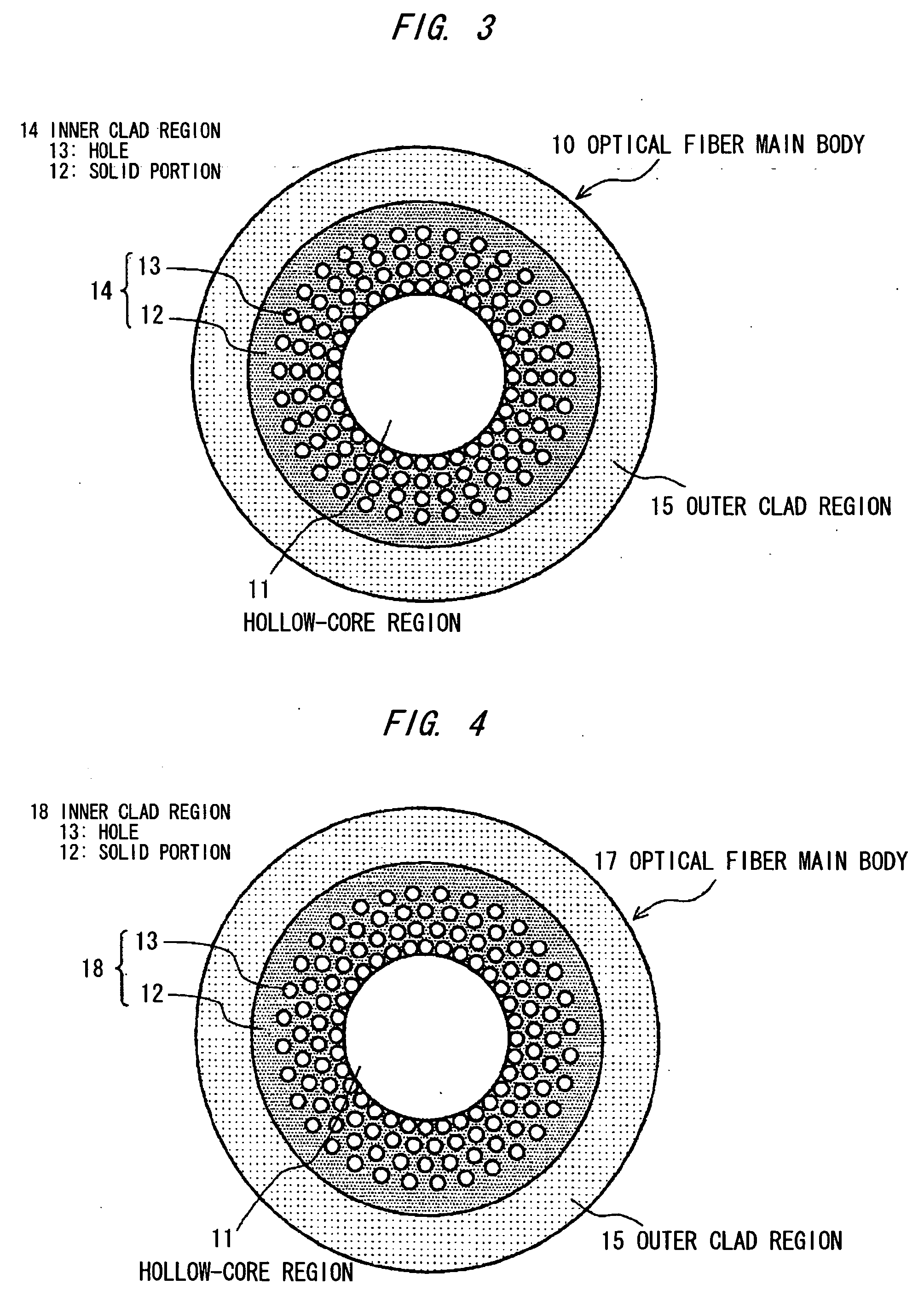
[0053]FIG. 3 is a cross sectional view showing a laser energy transmission optical fiber in the first preferred embodiment according to the invention.

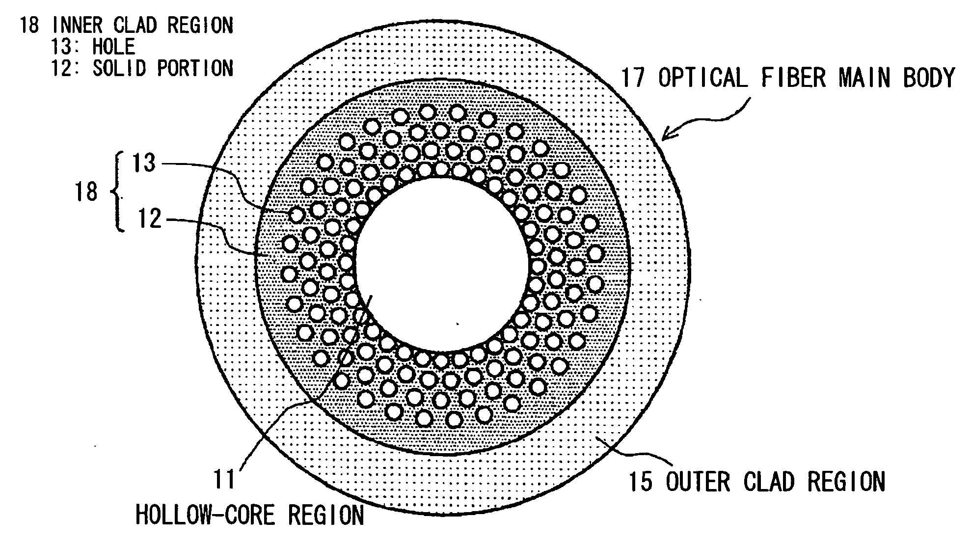
[0054] The laser energy transmission optical fiber of this embodiment is a hollow-core type optical fiber and comprises an optical fiber main body 10. In detail, as shown in FIG. 3, the optical fiber main body 10 comprises a hollow-core region 11, an inner clad region 14 formed surrounding the hollow-core region 11, and an outer clad region 15 formed surrounding the inner clad region 14. The hollow-core region 11 has an inside diameter greater than a wavelength of transmitted light. The inner clad region 14 has a solid portion 12 with plural holes 13 formed therein.

[0055] The plural holes 13 are arranged such that the holes are on plural concentric circles, the holes of same number are formed at equal intervals on each circle, and the holes are aligned in its radial direction. By thus arranging the holes 13, the inner clad region 14 ...

second embodiment

[0067]FIG. 5A is a longitudinal cross sectional view showing a laser energy transmission optical fiber in the second preferred embodiment according to the invention. FIG. 5B is a cross sectional view cut along a line B-B in FIG. 5A, and FIG. 5C is a cross sectional view cut along a line C-C in FIG. 5A.

[0068] As shown in FIGS. 5A to 5C, the laser energy transmission optical fiber 20 of this embodiment comprises the optical fiber main body 10 as shown in FIG. 3 and a solid-core type optical fiber 21 of short length.

[0069] In the laser energy transmission optical fiber 20, the solid-core type optical fiber 21 of short length is fusion-bonded to one or both ends of the optical fiber main body 10.

[0070] The solid-core type optical fiber 21 comprises a solid-core region 25, and a clad region 26 formed surrounding the solid-core region 25. In order that the solid-core region 25 can have a refractive index higher than the clad region 26, the solid-core region 25 is made of pure silica an...


PUM


Abstract

A laser energy transmission optical fiber having an optical fiber main body which has a hollow-core region with a diameter greater than a wavelength of transmitted light, an inner clad region which has a solid portion with plurality of holes formed therein, and an outer clad region formed surrounding the inner clad region. The outer clad region has a refractive index lower than the solid portion of the inner clad region.

Description

[0001] The present application is based on Japanese patent application No. 2005-019481, the entire contents of which are incorporated herein by reference. BACKGROUND OF THE INVENTION [0002] 1. Field of the Invention [0003] This invention relates to an optical fiber for transmitting laser energy and, in particular, to an optical fiber that is suited to transmit high-output laser light with an infrared wavelength band which is useful for medical applications. This invention also relates to a laser energy transmission method and a laser energy transmission device using the optical fiber. [0004] 2. Description of the Related Art [0005] In recent years, according as semiconductor lasers or solid-state lasers are provided with a higher output or shorter pulse, various uses have been developed using laser energy with high peak power. Especially, the use for laser processing or a laser surgery attracts attention. [0006] Conventionally, a silica optical fiber 30 with a large diameter as show...

Claims


Application Information

Patent Timeline
IPC IPC(8): G02B6/032
CPCG02B6/02328G02B6/02357G02B6/02361G02B6/032G02B6/102
Inventor HONGO, AKIHITO
Owner HITACHI CABLE
Why Eureka
Try Eureka