[0007]The recast layer and heat-affected zone thickness are greatly reduced when using
nanosecond pulses over
millisecond and
microsecond wide laser pulses (XiangLi Chen and Xinbing Liu; Short
Pulsed Laser Machining: How Short is Short Enough, J.
Laser Applications, Vol. 11, No. 6, December 1999). These improvements result from the higher laser beam intensity associated with the higher peak powers that are obtained with shorter laser pulses that utilize Q-switching,
mode locking and other associated techniques and the fact that the
pulse duration is shorter than the thermal
diffusion time. For example, the typical thermal
diffusion time for a 250 micron
diameter hole is approximately 0.1
millisecond. In
spite of the lower energy per pulse, high drilling speeds can still be cost effectively obtained because of the high pulse repetition rate obtained with these technologies. The high laser beam intensity provided by short laser pulses technology results in
vaporization-dominated
material removal rather than the melt-expulsion-dominated mechanisms using
millisecond wide laser pulses. It is also known that shorter pulse width yield more limited heat
diffusion into the surrounding material during the laser pulse. Hole-to-hole dimensional stability is also improved because the hole is drilled by the material being nibbled away by tens to hundreds of laser pulses of smaller
pulse energy but occurring at a high
pulse repetition frequency rather than by a few high-energy pulses. For the same reason, thermal and mechanical shocks from
nanosecond pulses are also reduced compared with millisecond pulses. These advantageous effects obtained with
nanosecond laser pulses have been detected by observing fewer micocracks occurring when holes were drilled in brittle materials such as
ceramic and glass when utilizing
nanosecond laser pulses.
[0008]When the intensity is further increased through laser
mode locking techniques to get down to the subnanosecond pulse width (i.e. picoseconds and
femtosecond region), additional reductions in the recast and heat-affected zones are observed. Since a typical
electron energy transfer time is in the order of several picoseconds,
femtosecond laser
pulse energy is deposited before any significant
electron energy transfer occurs within the
skin depth of the material. This forms a
plasma that eventually explodes and evaporates the material leaving almost no melt or heat-affected zone. Due to the small energy per pulse (˜1 mJ), any shock that is generated is weak resulting in no microcracks even in brittle
ceramic alumna material.
Femtosecond pulses are not presently obtainable with CO2 lasers due to the narrow
gain of the
laser line.
Femtosecond pulses are presently obtainable with
solid-state lasers.
[0009]For the same total irradiated laser energy,
femtosecond pulses remove two to three times more material than the nanosecond pulses. However, even “hero” type, one of a kind experimental, state of the art laser research and development systems that operate in the femtosecond range deliver only several watts of average power, while nanosecond lasers yield one or two
order of magnitude higher power output. Consequently, femtosecond lasers are still too low in average power to deliver the required
processing speeds for most commercial applications. It has been reported (XiangLi Chen and Xinbing Liu; Short
Pulsed Laser Machining: How Short is Short Enough, J.
Laser Applications, Vol. 11, No. 6, December 1999) that a 1W femtosecond laser requires more than a minute to
drill a 1.0 mm
deep hole of 0.1 mm
diameter. Present femtosecond lasers have such high cost that their use is cost effective for only special high value applications that unfortunately have relative low
unit volume market potential. For example, Lawerance Livermore National Lab has made use of the fact that femtosecond laser
pulse energy is deposited essentially with no
thermal transfer to
cut and shape
highly sensitive explosive materials without denotation.
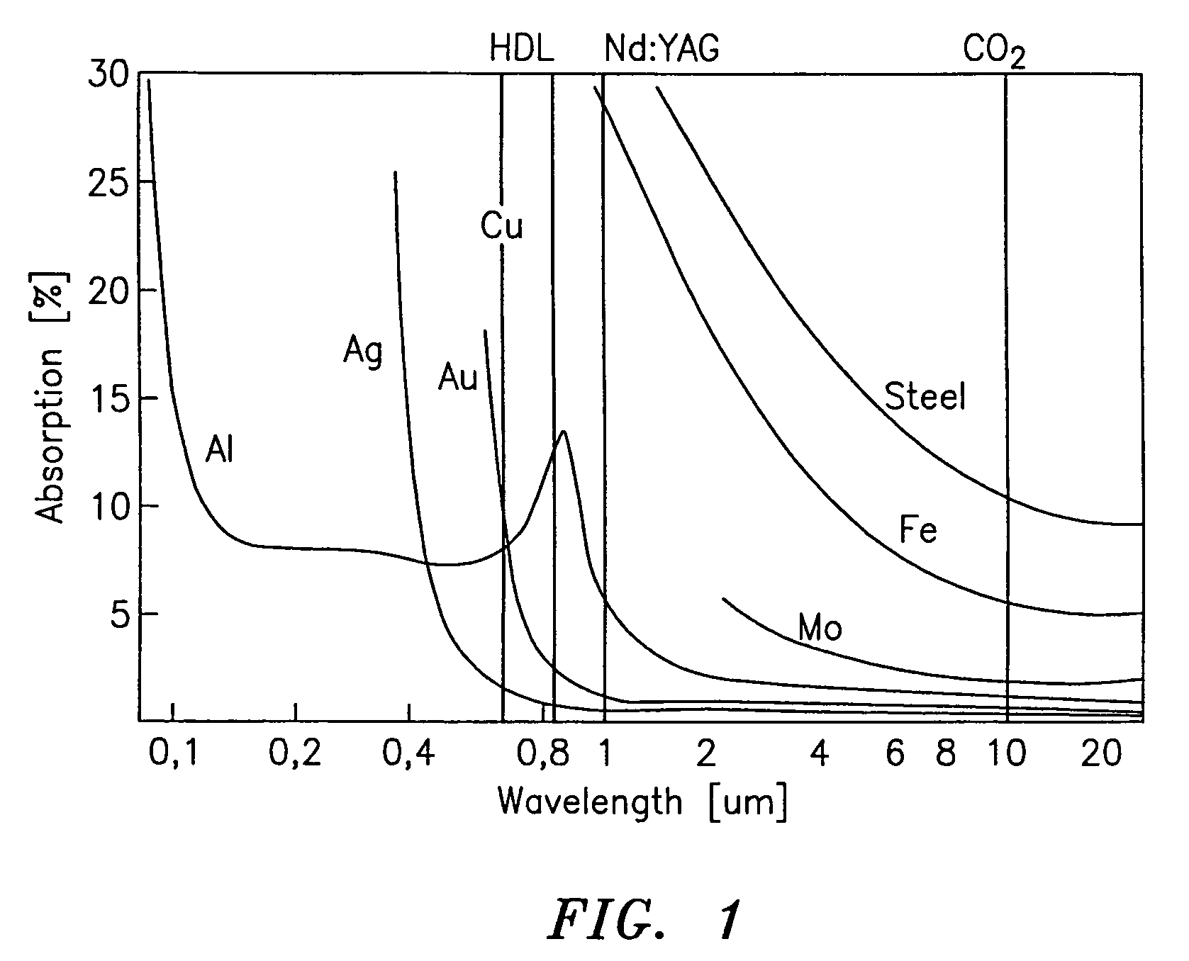
[0010]It is well known that the trend for optical absorption in metals as a function of
wavelength is toward lower absorption with increasing wavelengths as shown in FIG. 1. Consequently, the near IR, visible and ultra violet
wavelength regions are most effective in
machining most metals. This
advantage does not exist in plastic material. The data contained in FIG. 1 is not relevant once a
plasma is initiated on the
metal surface because all of the laser energy is absorbed in the
plasma, which in turn imparts the energy to the material. Once the plasma is initiated, the absorption as a function of wavelength variation for metals becomes essentially flat. Consequently, one can paint the surface of the
metal for greater absorption at longer wavelengths and the higher absorption
advantage of shorter laser wavelengths is effectively eliminated.
[0011]The
electronics industry has needs to shrink the size of
semiconductor and
hybrid packages, and greatly increase the density of printed circuit boards because of the market desire for smaller cellular phones,
paging systems, digital cameras, lap top and
hand held computers, etc. These needs have resulted in interest in the use of lasers to form small vertical layer-to-layer electrical paths (via) in printed circuit boards. The short pulse CO2 laser is particularly attractive for drilling via holes in printed circuit boards because of 1) the
high absorption of the
printed circuit board or
hybrid circuits resin or
ceramic material at the CO2 wavelength when compared to YAG or YLF lasers which operate in the near IR and in the visible and UV wavelength regions with
harmonic generating technique; 2) the lower cost per watts associated with CO2 lasers when compared to YAG lasers, 3) and because of the
high reflectivity of
copper at CO2 wavelengths, which enables CO2 laser via hole drilling equipment to
drill through the resin layer down to the
copper layer where the drilling is stopped because of the
high reflectivity of the
copper interconnect material at the CO2 laser wavelengths. These are called “blind via,” which connect the outer layer of a circuit to the underlying inner layer within the multi layer board. The major disadvantages of CO2 lasers in via hole drilling is the larger spot size obtainable with its 10.6 micron wavelength when compared to shorter wavelength laser. Another
disadvantage is that pulse widths below several nanosecond are difficult to obtain with CO2 lasers. The major advantages of CO2 Q-switched lasers are: they offer lower cost per
watt of laser output when compared with
solid state lasers, the higher absorption of their
radiation by resin and ceramic board materials, their ability to operate at high PRF, their ability to generate substantial output power under Q-switched operation, and their ability to stop drilling when the
radiation gets to the copper layer.
[0012]The advantages of drilling via holes in printed circuit boards with laser systems have enabled laser systems to capture 70% of the via hole
machine drilling market in 1999 (David Moser;
Laser Tools For Via Formation, Industrial Laser Solutions, p. 35, May, 2000, which is incorporated herein by reference), with the remaining 25% of the market held by photo-via and the remaining 5% by other techniques, such as mechanical drilling, punch and
plasma etching.

