Multi-photon lithography

a multi-photon, lithography technology, applied in the field of photolithography, can solve the problems of high peak-power pulses still damaging materials and/or structures placed in optical beams, destroying optical beams, damaged or reflective masks illuminated by high peak-power pulses, etc., to achieve the effect of improving image resolution and improving feature definition in exposed photoactive materials

Inactive Publication Date: 2005-11-17
CHROMAPLEX
View PDF11 Cites 36 Cited by
  • Summary
  • Abstract
  • Description
  • Claims
  • Application Information

AI Technical Summary

Benefits of technology

[0009] Embodiments of the invention can include one or more of the following features. The photoactive material can be a photon-activatable photoacid generator that can be activated by single-photon, two-photon, or multi-photon processes, with the light source being a pulsed laser. The wavelength exposing the photoactive material can be shorter than the laser emission wavelength and can be generated, for example, by optical frequency conversion, such as second or third harmonic generation. The pulse stretcher and the pulse recompressor can each include an optical grating pair that preferably operates in first order. The pulse stretcher can also be made of a suitable length of optical fiber. The mask can be a programmable mask, for example, a mask composed of arrays of movable micro-mirrors. To shape the wavefront and / or delay the phase of the stretched beam, a liquid crystal modulator can be placed in the optical beam path. The imaging resolution can be further enhanced by placing an index matching fluid between the optical element and the photoactive material.
[0010] The feature definition in the exposed photoactive material can be improved by micro-stepping or interleaving mask patterns by repeatedly imaging the recompressed illuminated pattern onto the photoactive medium with a relative offset between imaging steps, wherein a resulting separation between pattern features produced from different imaging steps is smaller than a diffraction-limited image of the pattern features.

Problems solved by technology

However, even with a pulsed laser light source with short pulse duration in the order of picoseconds to femtoseconds and a relatively low average power, the high peak-power pulses can still damage materials and / or structures placed in the optical beam.
For example, a transmissive or reflective mask illuminated by a high peak-power pulse optical beam may be damaged and even destroyed by the intense optical and electrical field produced by the illuminating beam.

Method used


Image

  • Multi-photon lithography
  • Multi-photon lithography
  • Multi-photon lithography

Examples


Embodiment Construction

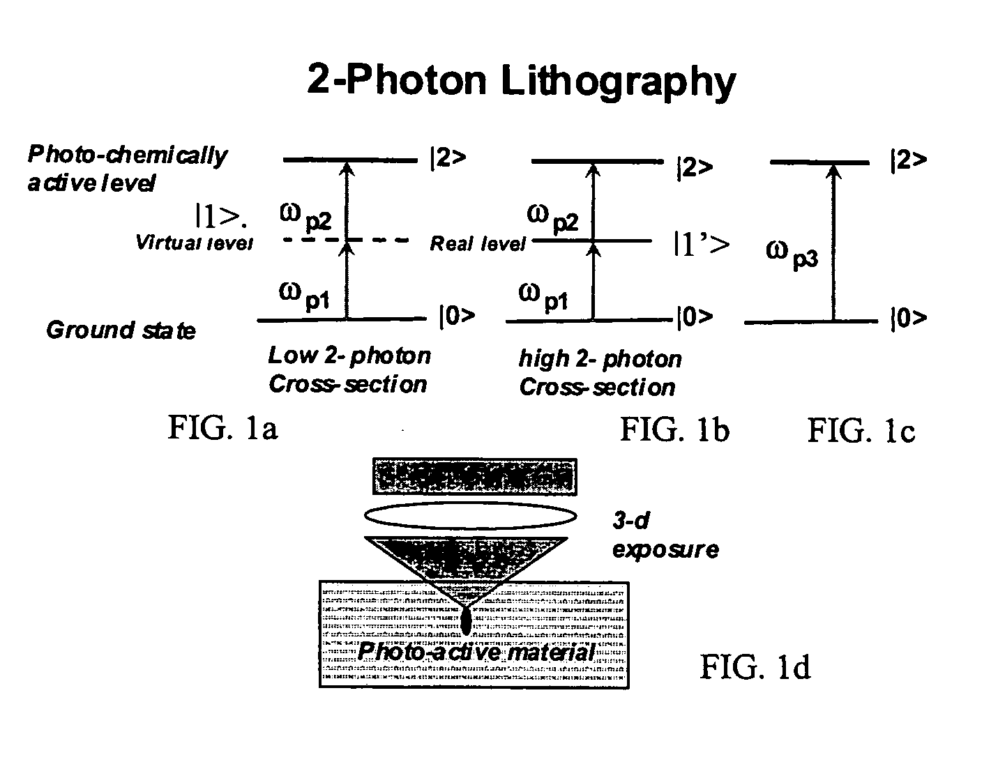
[0020] The system described herein is directed to patterning a photoactive material, such as photoresist, applied on, for example, a wafer with a high peak-intensity optical beam, wherein the exposure is induced by simultaneously absorbing two photons which in the illustrated example have the same photon energy. In particular, the system described herein uses an optical projection-reduction system, similar to a projection mask aligner. However, unlike a conventional system, the short duration pulses of the exciting optical beam are first stretched to form pulses of longer duration with a smaller peak energy to prevent damage to the mask. These longer pulses then illuminate a patterned mask, whereafter they are recompressed, e.g., by another grating pair, and imaged onto the photoactive medium, such as photoresist, for example by a reduction optical system.

[0021]FIGS. 1a to 1d show schematically a two-photon process in an optically absorbing material. Photons having photon energies ...


PUM

PropertyMeasurementUnit
sizesaaaaaaaaaa
exposure wavelengthaaaaaaaaaa

Abstract

A system and method for patterned exposure of a photoactive medium is described wherein a pulsed optical beam with a high peak-power is stretched in the time domain to reduce the peak power while maintaining the average power. The stretched pulse illuminated a pattern, such as a transparent or reflective photolithography mask. The pattern is then imaged onto the photoactive medium after recompressing the beam. This arrangement prevents damage to the mask by the high peak power of the pulsed optical beam.

Description

BACKGROUND OF THE INVENTION [0001] The invention relates to photolithography in general, and more particularly to a device and method for producing two- and three dimensional patterned structures with a photolithography mask by a multi-photon optical process. [0002] Non-linear optical processes can occur in molecular and atomic structures when the focused optical field reaches an optical power density of approximately 108 W / cm2. Such non-linear optical processes can include frequency conversion caused by higher order effects in the electric susceptibility as well as multi-photon absorption. [0003] Because nonlinear optical and multi-photon processes are super-linear, they require a high optical power density in the material of interest to achieve a high efficiency. However, even with a pulsed laser light source with short pulse duration in the order of picoseconds to femtoseconds and a relatively low average power, the high peak-power pulses can still damage materials and / or structu...

Claims


Application Information

Patent Timeline
Patent Type & Authority Applications(United States)
IPC IPC(8): G03B27/54G03F7/20
CPCG03F7/7055G03F7/70041
Inventor FRANKEL, ROBERT
Owner CHROMAPLEX
Why Eureka
Try Eureka