Method of manufacturing an optical module

a manufacturing method and optical module technology, applied in the field of optical modules, to achieve the effect of simplifying the process, reducing the cost, and simplifying the process

Inactive Publication Date: 2009-07-14
TOYODA GOSEI CO LTD
View PDF12 Cites 3 Cited by
  • Summary
  • Abstract
  • Description
  • Claims
  • Application Information

AI Technical Summary

Benefits of technology

[0011]Thereupon, the inventors have earnestly examined an optical module having a self-forming type core in a different configuration from those of FIGS. 4A to 4E and have finally completed the invention. That is, an object of the invention is to provide an optical module in which the bonding between a core made of cured resin and an optical device is not easily deteriorated.
[0018]The invention makes it possible to provide an optical module that uses a self-forming type core, wherein the core and optical devices are not easily separated. According to the invention, the optical devices can be pre-aligned in position, so that the process is simplified, thus enabling a reduction in cost. Besides, since a resin reservoir for a curable resin for core formation and a mold for clad formation are made common, the process can be simplified. Besides, the core can be bonded directly to the optical devices and not via the casing, thus improving bonding efficiency, so that a device life can be lengthened and a deterioration in characteristics can be suppressed.
[0019]The detachable fixing member may be detached at any step, but when it is detached before the uncured resin removal step, the uncured resin can be properly removed. When the cladding material uses a light or heat curable resin, especially a liquid one, the core can be fully covered therewith, thus making it possible to restrain light from leaking through a core surface. The cladding material also covers the mirrors, half mirrors, and other optical components, the main portions of the optical devices, and the vicinity of the emitting end of the optical waveguide, thereby making it possible to provide a strong optical module that is difficult to break.
[0020]Besides, the core can be bonded directly to the optical devices and not via the casing, thus improving bonding efficiency, so that a device life can be lengthened and a deterioration in characteristics can be suppressed.

Problems solved by technology

With such a structure, it turns out, the following problem arises when a life and a deterioration in characteristics as a module are evaluated based on a so-called acceleration test.

Method used


Image

  • Method of manufacturing an optical module
  • Method of manufacturing an optical module
  • Method of manufacturing an optical module

Examples


first embodiment

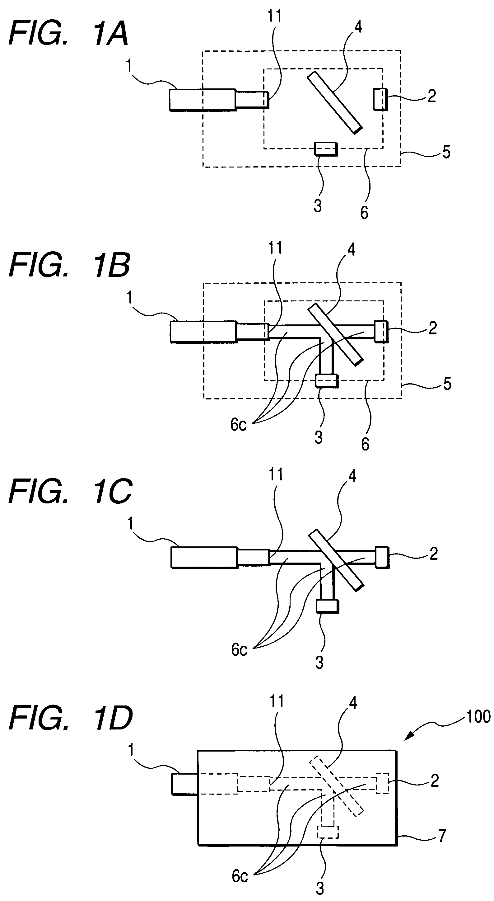
[0030]FIGS. 1A to 1D are process diagrams showing in conceptual form a manufacturing method according to a first embodiment of the invention. First, a POF 1, a green PD (light receiving device) 2, a red LED (light emitting device) 3, and a wavelength selective mirror 4 are prepared. The method uses the wavelength selective mirror 4 that reflects red light and transmits green light. These optical components are disposed on a fixing member 5 to which are fixed a core end face 11 of the POF 1, a light receiving surface of the light receiving device 2, a light emitting surface of the light emitting device 3, and a reflective surface of the wavelength selective mirror 4, and from which the optical components are detachable. The fixing member 5 is configured such that a light curable resin solution 6 to provide a core can be disposed thereon between the core end face 11 of the POF 1 and the lower left surface of the wavelength selective mirror 4, between the upper right surface of the wav...

second embodiment

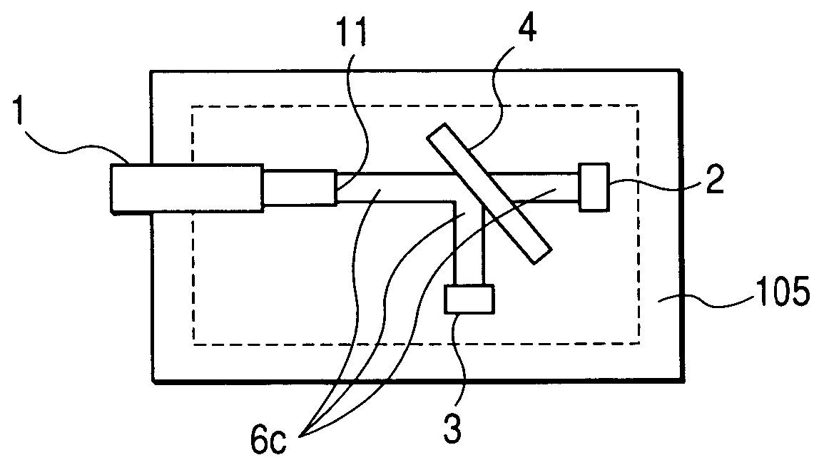
[0040]FIGS. 5A to 5D are process diagrams showing in conceptual form a manufacturing method according to a second embodiment of the invention. First, a POF 1, a green PD 2, a red LED 3, and a wavelength selective mirror 4 are prepared. The method uses the wavelength selective mirror 4 that reflects red light and transmits green light. The individual components are arranged within a mold 105 in such a way that the core end face 11 of the POF 1 is fixed by the mold 105, and that the light receiving face of the light receiving device 2, the light emitting face of the light emitting device 3 and the reflective surface of the wavelength-selective mirror 4 are temporarily fixed by jigs not shown. By the way, whereas FIG. 4 depicts side views showing the process in a horizontal direction, the respective views of FIG. 5 are side views showing the process from above. Within the mold 105 indicated by a broken line in FIG. 5, a curable resin liquid 6 to become a core could be arranged. Inciden...


PUM

PropertyMeasurementUnit
core diameteraaaaaaaaaa
wavelengthaaaaaaaaaa
refractive indexaaaaaaaaaa

Abstract

There is provided a method of manufacturing an optical module comprises a component fixing step in which an optical waveguide and at least one optical device are detachably held by a fixing member capable of holding an uncured light curable resin in a required position, and a core forming step in which light of a wavelength for curing the light curable resin is emitted from the leading end of the optical waveguide to the light curable resin uncured and thus the light curable resin is cured to form a shaftlike core. According thereto, the optical waveguide and the optical device are connected by the core.

Description

[0001]This application is based on Japanese Patent Application No. 2004-164084 and 2005-095568, which are incorporated herein by reference.BACKGROUND OF THE INVENTION[0002]1. Field of the Invention[0003]The present invention relates to an optical module that has a core fabricated using a light curable resin solution and light, and to a method of and an apparatus for manufacturing the optical module. The invention is applicable to an inexpensive and low-loss optical module for use in optical fiber communications, such as an optical transmitter and receiver, an optical interconnection device, and an optical branching filter or coupler.[0004]2. Description of the Related Art[0005]The inventors, together with their coinventors, have developed and applied for patent on an optical waveguide having a so-called self-forming type core. The self-forming type core forms the optical waveguide in the following manner. That is, for example, a liquid light curable resin uncured is irradiated with ...

Claims


Application Information

Patent Timeline
Patent Type & Authority Patents(United States)
IPC IPC(8): B29D11/00G02B6/12G02B6/138G02B6/34G02B6/42
CPCG02B6/138G02B6/4246G02B2006/12164
Inventor INUI, YUKITOSHITERADA, KAZUHIROKOMADA, MINORUMAENO, TAKASHI
Owner TOYODA GOSEI CO LTD
Why Eureka
Try Eureka