Devices and methods for LED life test
a life test and led technology, applied in the field of life test equipment for semiconductor elements, can solve the problems of relative longer lifetime, inability to achieve lifetime tests for a short period, and inability to control the temperature of led
- Summary
- Abstract
- Description
- Claims
- Application Information
AI Technical Summary
Problems solved by technology
Method used
Image
Examples
first embodiment
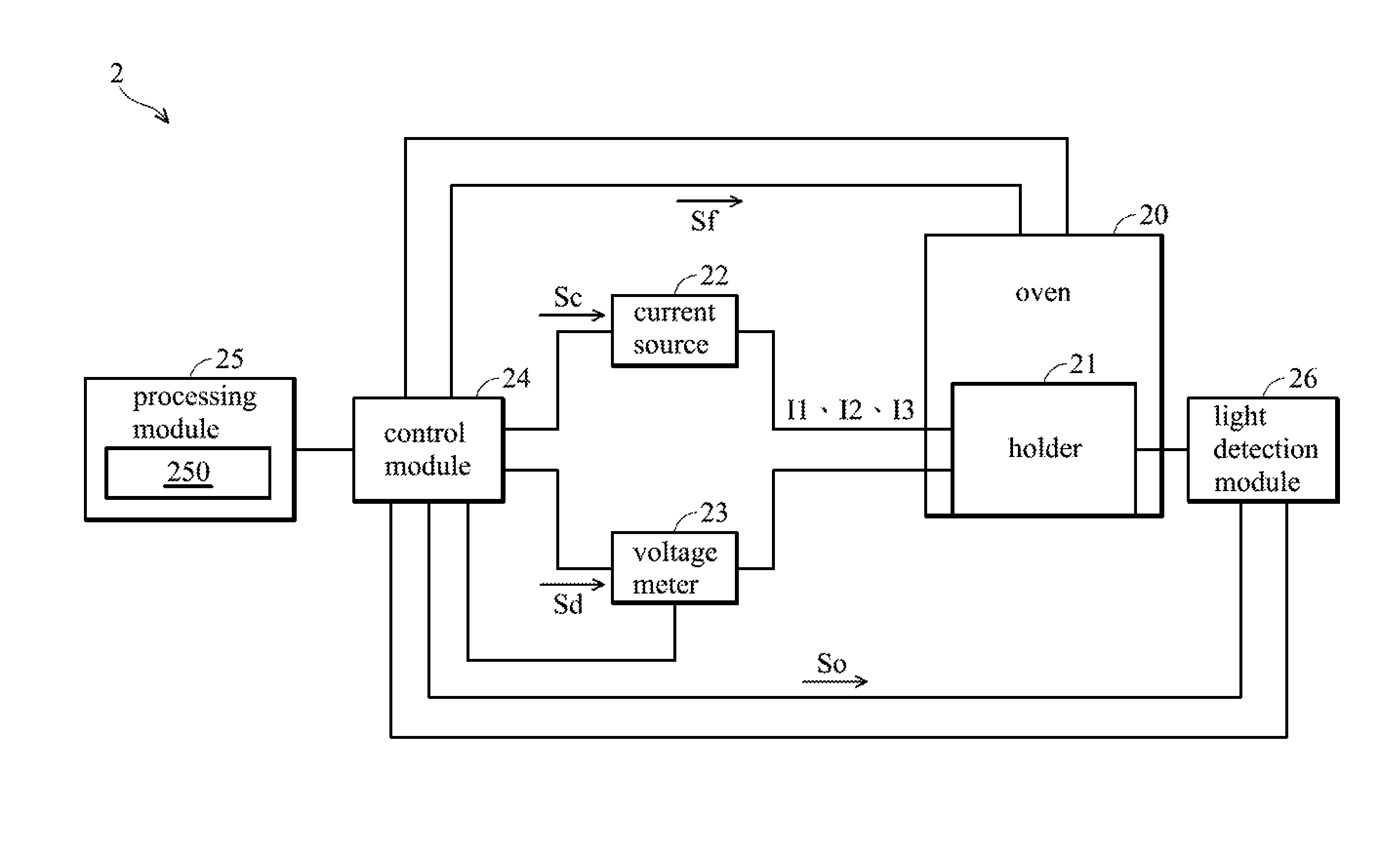
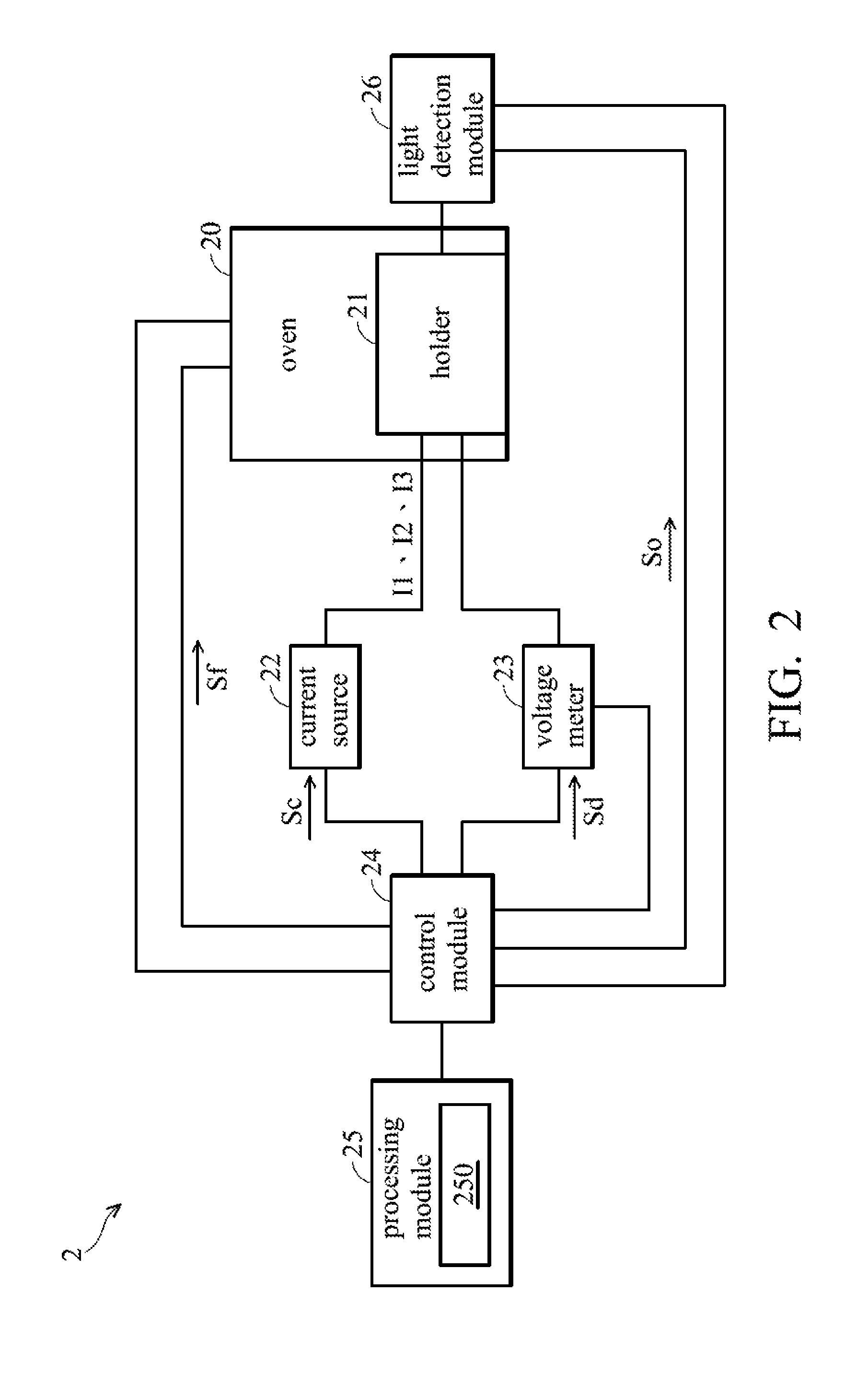
[0025]FIG. 2 shows the first embodiment of a lifetime test equipment. Referring to FIG. 2, a lifetime test equipment 2 is used to test lifetime of an LED and comprises an oven 20, an LED holder 21 disposed in the oven 20, a current source 22, a voltage meter 23, a control module 24, a processing module 25, and a light detection module 26. The LED is disposed on the holder 21. The control module 24 provides a current control signal Sc to the current source 22. The control module 24 also provides a voltage measurement signal Sd for controlling the voltage meter 23 to measure a forward voltage generated by the LED and transmit the measured forward voltage to the processing modules 25. The control module 24 provides a light detection signal So for controlling the light detection module 26 to detect light output of the LED and transmit the detected light output to the processing module 25. The control module 24 further provides an oven-temperature detection signal Sf for detecting a temp...
second embodiment
[0040]According to the second embodiment, the junction temperature of the LED can be obtained by another variation relationship equation between the forward voltages and the oven temperature points. During the period P1, when the processing module 25 obtains the forward voltages V1 and V2 and the oven temperature points T1 and T2, a variation relationship equation between forward voltages V1 and V2 and the oven temperature points T1 and T2 is obtained:
V=A*T+B (3)
[0041]wherein V represents a forward voltage, T represents an oven temperature point, A represents the slope of the variation relationship equation (3), and B represents the intercept of the variation relationship equation (3). According to Equation (2) and Equation (3), the slope A of the variation relationship equation (3) is the temperature coefficient K.
[0042]During the period P2, the current source 22 is switched to provide the current I2 to the LED for a decay test according to the current control signal Sc. After eve...
third embodiment
[0045]FIG. 5 shows the third exemplary embodiment of a lifetime test equipment. The elements with the same references as in FIGS. 2 and 5 perform the same operations. The lifetime test equipment 5 of FIG. 5 is similar to the lifetime test equipment 2 of FIG. 2, and the difference there between is that the lifetime test equipment 5 is used to test lifetime of a plurality of LEDs. Moreover, the currents I1 and I3 and the current I2 are provided by different current sources. Referring to FIG. 5, the lifetime test equipment 5 comprises an oven 20, an LED holder 21 disposed in the oven 20, current sources 51 and 52, a power switch unit 53, a voltage meter 23, a control module 24, a processing module 25, and a light detection module 26. The LEDs are disposed on the LED holder 21. The control module 24 provides a current control signal Sc1 to the current source 51 and a current control signal Sc2 to the current source 52. The control module 24 provides a voltage measurement signal Sd for c...
PUM
 Abstract
Description
Claims
Application Information
 - R&D
- Intellectual Property
- Life Sciences
- Materials
- Tech Scout
- Unparalleled Data Quality
- Higher Quality Content
- 60% Fewer Hallucinations
Browse by: Latest US Patents, China's latest patents, Technical Efficacy Thesaurus, Application Domain, Technology Topic, Popular Technical Reports.
© 2025 PatSnap. All rights reserved.Legal|Privacy policy|Modern Slavery Act Transparency Statement|Sitemap|About US| Contact US: help@patsnap.com


