Winshield wiping device

Inactive Publication Date: 2011-02-22
ROBERT BOSCH GMBH
View PDF9 Cites 34 Cited by
  • Summary
  • Abstract
  • Description
  • Claims
  • Application Information

AI Technical Summary

Benefits of technology

[0004]The advantage of the windshield wiper device is that the embodiment of the predetermined breaking point as a hole makes it possible to adjust in a much more precise manner the force necessary to separate the wiper bearing from the body of the vehicle. In this way, the impact behavior, i.e., the behavior of the windshield wiper device during an impact of a pedestrian on the wiper shaft, can also be adjusted in vehicle-specific way. In addition, this embodiment is cost-effective and particularly practical for series production since the wiper bearings can be fabricated in large unit numbers and then the predetermined breaking points can be introduced in the fastening element individually for each vehicle type.
[0005]It is particularly advantageous if the fastening element is embodied as a plate-like projection and is embodied as a one-part piece with the molded tube. As a result, the wiper bearing is simple and cost-effective to manufacture, e.g., in a diecasting method. This makes it unnecessary to use hinges, rivets, dowels or other fastening agents between the fastening element and the molded tube, which can be prone to interference in operation or could be damaged in the case of a pedestrian impact.
[0006]In another advantageous embodiment, the fastening element has at least one hole with a circular or oval cross section since holes can be made in the fastening element simply, easily and cost-effectively, whereby the defined impact force can be adjusted easily by the number and size of the holes.

Problems solved by technology

This makes it unnecessary to use hinges, rivets, dowels or other fastening agents between the fastening element and the molded tube, which can be prone to interference in operation or could be damaged in the case of a pedestrian impact.

Method used


Image

  • Winshield wiping device
  • Winshield wiping device
  • Winshield wiping device

Examples


Embodiment Construction

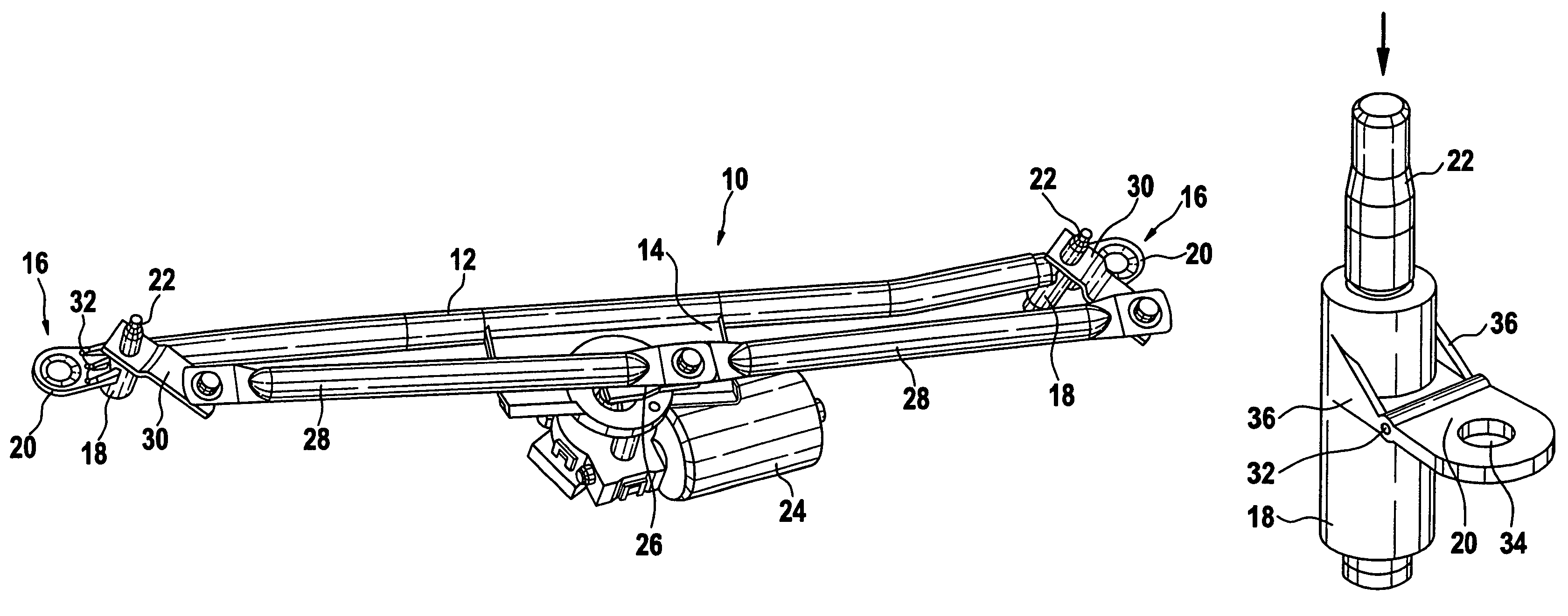
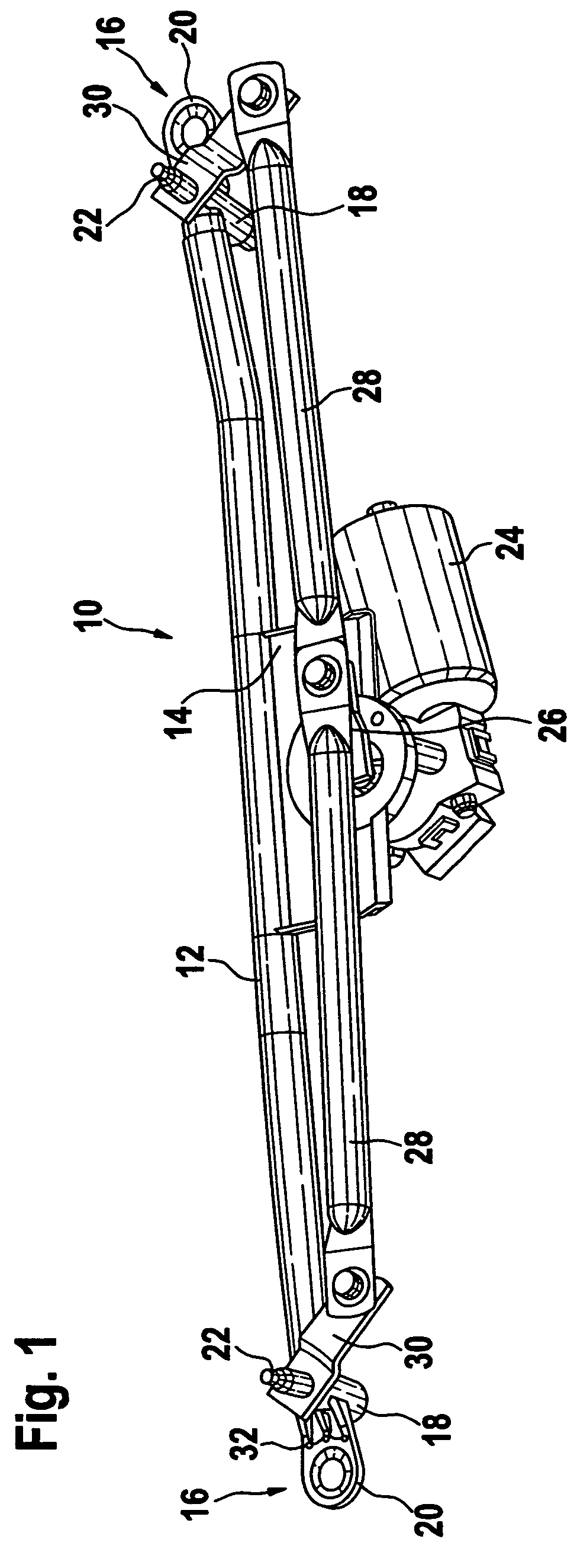
[0018]FIG. 1 shows a perspective representation of a windshield wiper device 10 in accordance with the invention.

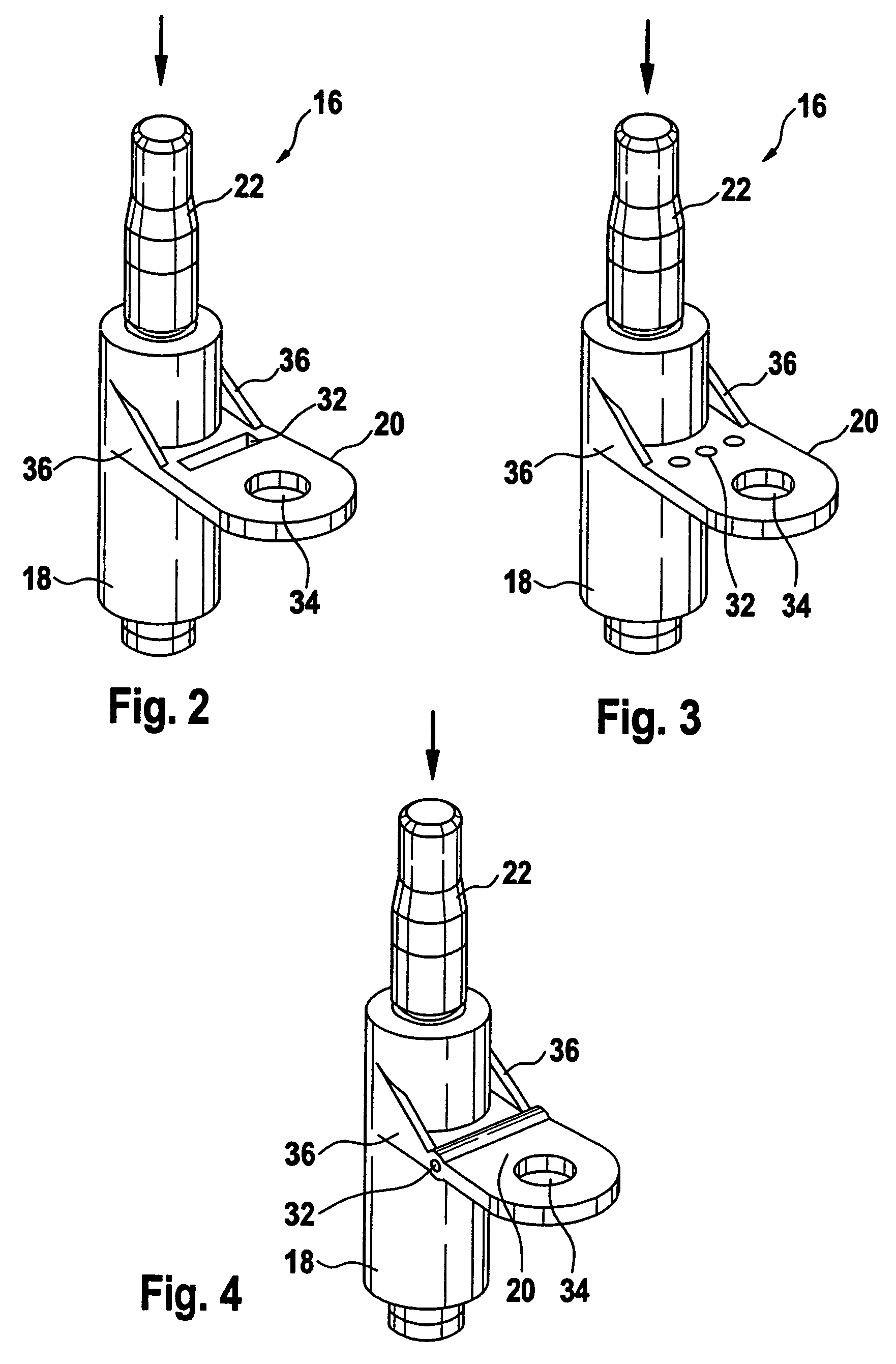
[0019]It is comprised essentially of a support tube 12 with a support mounting plate 14, which is embodied of sheet metal. Fastened on each end of support tube 12 is a wiper bearing 16, which has a molded tube 18 and a fastening element 20, which is used to fasten the windshield wiper device 10 to the motor vehicle.

[0020]Positioned in the molded tube 18 is the wiper shaft 22, which can be connected to wiper levers that are not shown here. In operation, these wiper levers move in a pendulum fashion over the window of the motor vehicle.

[0021]For this purpose, a drive 24 is fastened to the mounting plate 14, which has an output crank 26 to which the two thrust rods 28 are linked. The free ends of the thrust rods 28 are connected in a rotatably disposed manner to driving cranks 30, which are in turn each connected to a wiper shaft 22 in a rotationally secured manner. If the d...


PUM


Abstract

Disclosed is a windshield wiper device (10), comprising a wiper bearing (16) which is essentially composed of a molded tube (18) that can be fastened to a motor vehicle by means of a fastening element (20). A wiper shaft (22) to which a wiper lever can be fastened is positioned in the molded tube (18). A predetermined breaking point (32) is provided on the fastening element (20) in such a way that the wiper bearing (16) is able to dip into the interior of the motor vehicle in case a defined and essentially axial force acts on the wiper shaft (22). The predetermined breaking point (32) is embodied as a hole in this case.

Description

BACKGROUND OF THE INVENTION[0001]The invention relates to a windshield wiper device.[0002]Numerous windshield wiper devices are known, which have a wiper bearing with a molded tube and a wiper shaft positioned therein, on which a wiper lever can be fastened. These wiper bearings have a fastening element, which is embodied as a one-part piece with the molded tube and is used to fasten the windshield wiper device to the motor vehicle.[0003]This type of windshield wiper device is known from EP-A-0 739 792 in particular. The wiper bearings supporting the wiper shaft have a fastening element there, which is provided with a predetermined breaking point so that the wiper bearing can dip into the interior of the motor vehicle in the case of an impact of a pedestrian on the wiper shaft. The predetermined breaking points are embodied in this case as constrictions of the cross section of the fastening element. The embodiments shown there are expensive in terms of manufacturing, wherein in addi...

Claims


Application Information

Patent Timeline
Patent Type & Authority Patents(United States)
IPC IPC(8): B60S1/04
CPCB60S1/0488B60S1/043Y10T403/11Y10S403/03F16B2200/63B60S1/04
Inventor KRAUS, ACHIMRAPP, JUERGEN
Owner ROBERT BOSCH GMBH
Why Eureka
Try Eureka