Jamb saw

a jamb saw and saw blade technology, applied in the field of jamb saws, can solve the problems of inconvenient adjustment of cutting height, unfavorable holding and operation, etc., and achieve the effect of preventing relative rotary movement, efficient positioning and accurate operation of the jamb saw

Inactive Publication Date: 2011-02-22
BRADY MICHAEL L
View PDF18 Cites 15 Cited by
  • Summary
  • Abstract
  • Description
  • Claims
  • Application Information

AI Technical Summary

Benefits of technology

[0002]The invention is a hand held power tool for trimming door jambs and casing and particularly a jamb saw attachable to a power tool having a rotary output shaft. The jamb saw includes a circle saw blade secured to a shaft rotatably mounted in a cylindrical shaft support column which in turn is supported in a vertically split bushing portion of a blade housing in a vertically adjustable manner and the blade housing is supported on three floor engageable rollers. The shaft support column and the bushing portion have cooperating guide components permitting relative vertical movement and preventing relative rotary movement. After adjusting the height of the saw blade, by vertically adjusting the saw blade support column relative to the blade housing, the split bushing portion is contracted by rotating a threaded bolt interconnecting circumferentially confronting segments of the split bushing portion. Rotation of the bolt is effected by a hand held tensioning handle rigidly secured to the unthreaded end of the bolt. In using the jamb saw, one hand grips the power tool and the other hand grips the tensioning handle thereby facilitating efficient positioning and accurate operation of the jamb saw. A pair of roller arms have first ends pivotally mounted to the housing on vertical axes and second ends each supporting a floor engageable roller. The roller arms are biased to diametrically opposite positions relative to the saw drive shaft and are retractable against the bias during use of the jamb saw in making corner cuts. Releasable coupling components are provided on the upper end of saw shaft and the power tool output shaft.

Problems solved by technology

The jamb saws shown in the before mentioned patents and door jamb saws currently marketed are deficient in adaptability for connection to a power unit, are awkward to hold and operate and are not convenient to adjust the height of cut.

Method used


Image

  • Jamb saw
  • Jamb saw
  • Jamb saw

Examples


Embodiment Construction

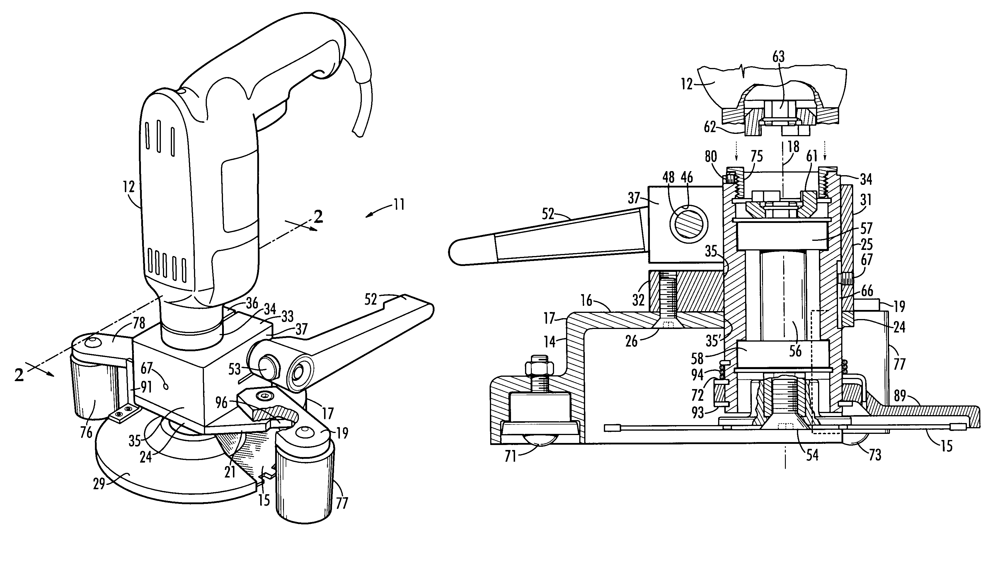
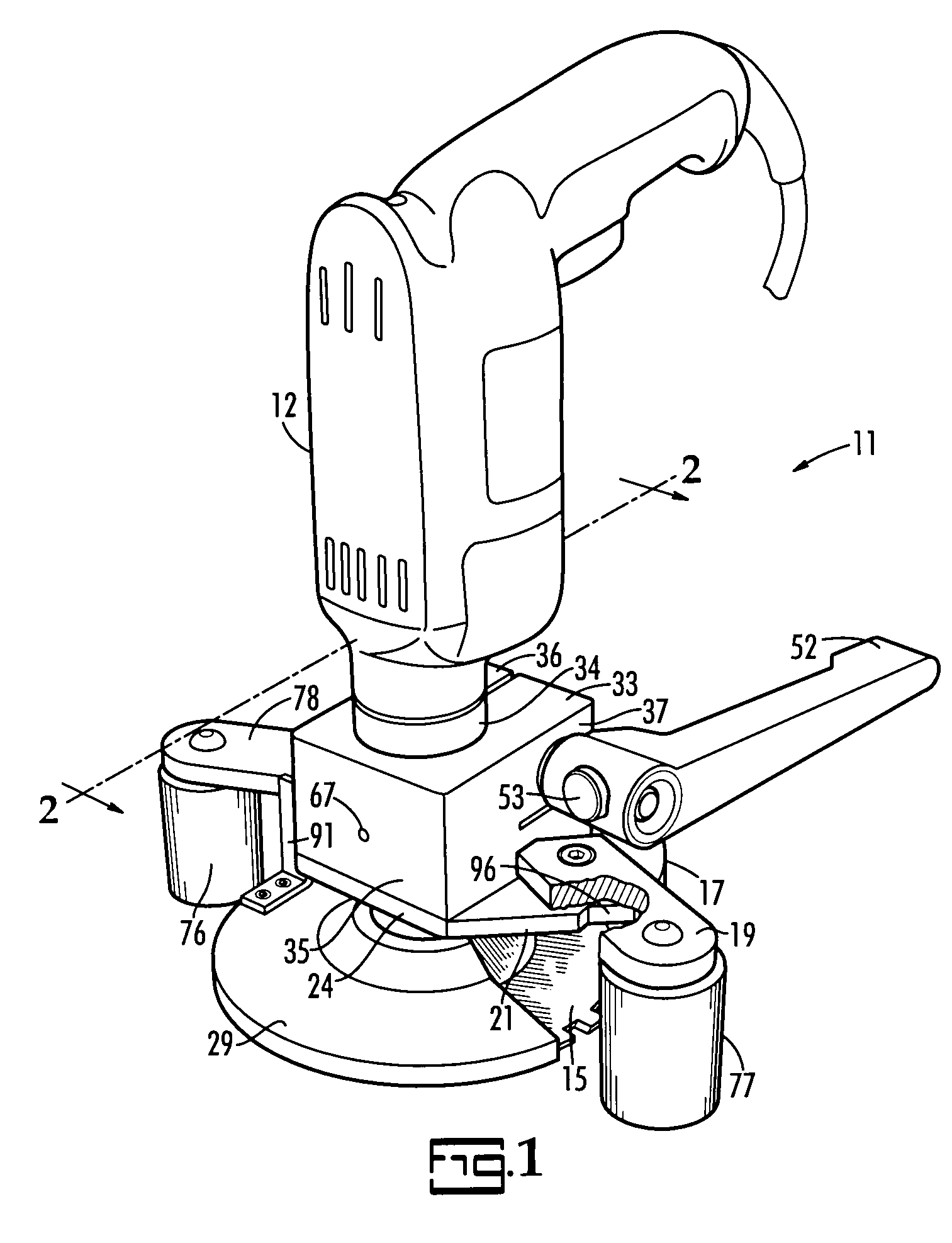
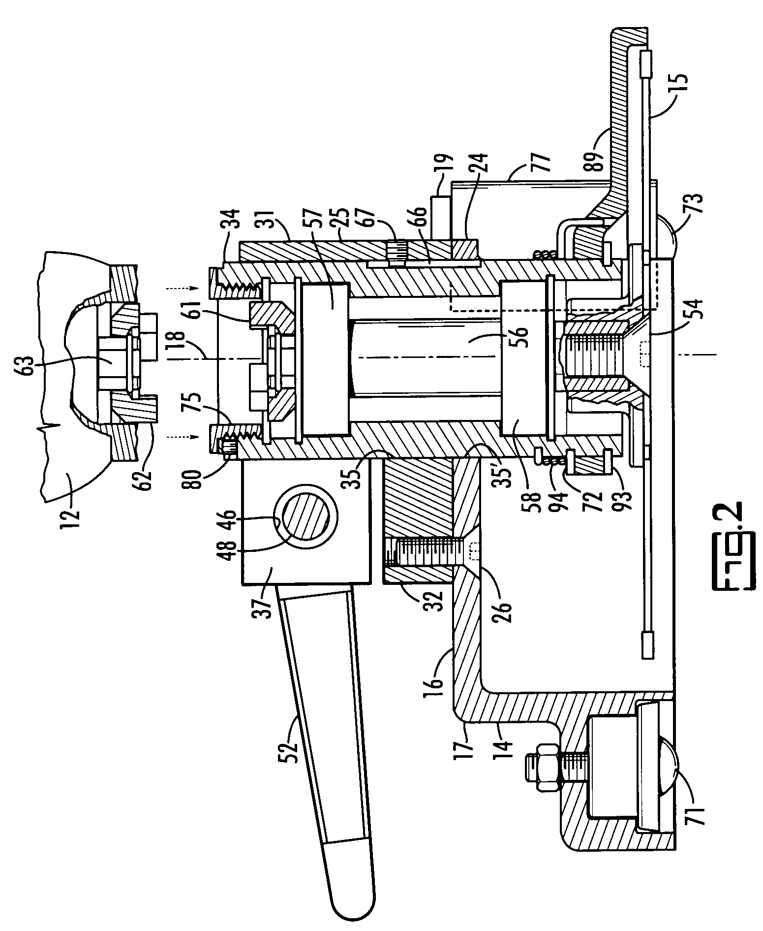
[0013]FIG. 1 shows the jamb saw 11 of this invention powered by a modified screw gun 12. Referring also to FIGS. 2, 3, 4, 9 and 10, the jamb saw 11 has a support structure 13 including a housing 14 partially sheltering a circular saw blade 15. The housing 14 includes a horizontal roof 16 having a 150 degree arc shaped edge 17 concentric with the axis 18 of the saw blade 15 and straight edges 21, 22 at a right angle to one another extending in a converging manner from the ends of the arc shaped edge 17. The roof 16 terminates in a forward edge 24 disposed at 45 degrees to the straight edges 21, 22 which terminate at equal distances from their theoretical point of convergence.

[0014]The housing 14 includes a block shaped bushing 31 having a lower part 32 which is rigidly secured by fasteners in the form of screws 26 to the roof 16 and includes a cylindrical vertical bore 35 concentric with a cylindrical vertical bore 35′ in the roof 16. The bores are concentric with the axis 18 of the ...


PUM

PropertyMeasurementUnit
angleaaaaaaaaaa
angleaaaaaaaaaa
distancesaaaaaaaaaa

Abstract

A powered jamb saw is provided which is ideally suited for making corner cuts. A cylindrical housing for the shaft of the circular saw blade is mounted in a split bushing tensioned by a threaded bolt secured to and for rotation by a handle positioned so as to permit the workman to use both hands to position the jamb saw during its use in making cuts.

Description

BACKGROUND OF THE INVENTION[0001]The invention relates to a powered hand tool for trimming door jambs and casings. Door jambs and casings are often installed before the flooring is laid and for that reason the door joints and casings must be trimmed to a predetermined distance above the sub-floor in order to install the flooring which extends beneath the door jambs and casings. U.S. Pat. Nos. 5,967,013 and 6,449,852 describe jamb saws described as useful for door jamb and casing trimming including trimming in corners. The jamb saws shown in the before mentioned patents and door jamb saws currently marketed are deficient in adaptability for connection to a power unit, are awkward to hold and operate and are not convenient to adjust the height of cut.SUMMARY OF THE INVENTION[0002]The invention is a hand held power tool for trimming door jambs and casing and particularly a jamb saw attachable to a power tool having a rotary output shaft. The jamb saw includes a circle saw blade secured...

Claims


Application Information

Patent Timeline
Patent Type & Authority Patents(United States)
IPC IPC(8): B27B5/08B27B5/00
CPCB23D45/003B23D47/02B27B5/08B27B5/30Y10T83/7755
Inventor BRADY, MICHAEL L.
Owner BRADY MICHAEL L
Why Eureka
Try Eureka