Centrifugal blower

a centrifugal blower and centrifugal technology, which is applied in the direction of liquid fuel engines, vessel construction, marine propulsion, etc., can solve the problem that the air inlet air intake rate is not easily affected, and achieve the effect of high operation efficiency

Active Publication Date: 2011-02-22
CORETRONIC
View PDF24 Cites 24 Cited by
  • Summary
  • Abstract
  • Description
  • Claims
  • Application Information

AI Technical Summary

Benefits of technology

[0010]The present invention is directed to providing a centrifugal blower having higher operation efficiency.
[0012]The anti-leakage element of the present invention extends from at least part of the edge of the inlet to the interior of the casing, so when the centrifugal blower of the present invention operates, the air pressurized by the blades within the casing does not easily leak. Therefore, the centrifugal blower of the present invention has higher operation efficiency.
[0013]Additionally, as the range of the anti-leakage element of the present invention extending to the interior of the casing is gradually reduced against the rotation direction in which the fan structure rotates, when the centrifugal blower operates, the air within the casing having a static pressure gradually increased in the rotation direction in which the fan structure rotates does not easily leak. Furthermore, the intake rate of air at the inlet is not easily affected to greatly decrease by the anti-leakage element.

Problems solved by technology

Furthermore, the intake rate of air at the inlet is not easily affected to greatly decrease by the anti-leakage element.

Method used


Image

  • Centrifugal blower
  • Centrifugal blower
  • Centrifugal blower

Examples


first embodiment

The First Embodiment

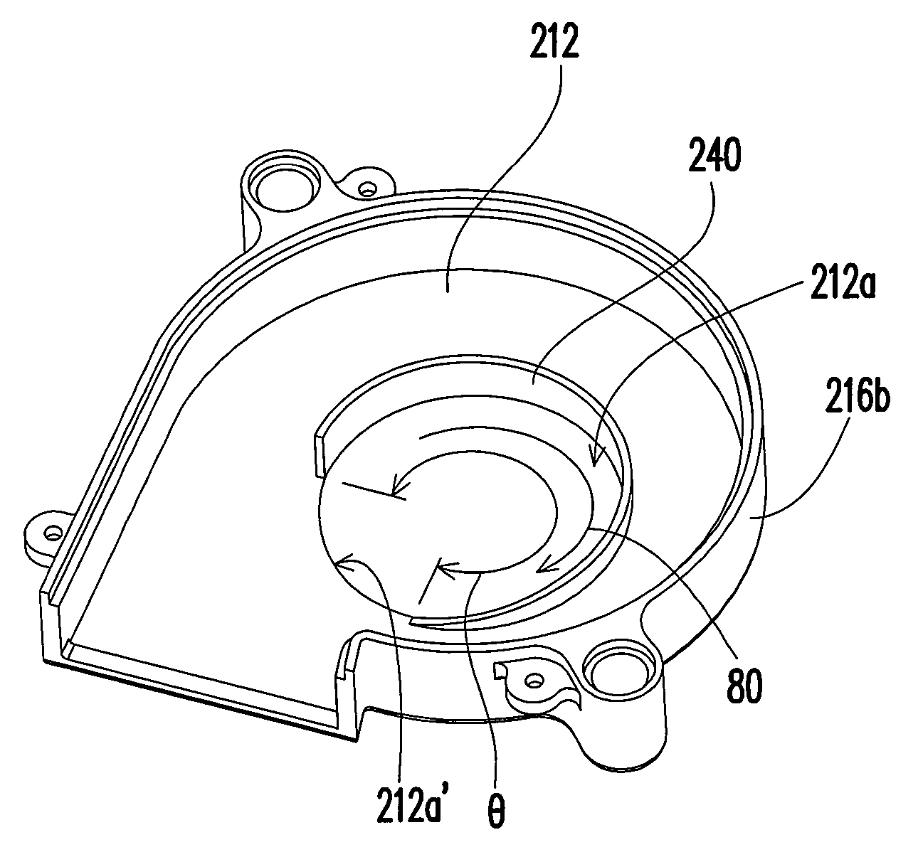
[0027]FIG. 2A is a schematic perspective view of a centrifugal blower according to a first embodiment of the present invention, FIG. 2B is a schematic top view of the centrifugal blower of FIG. 2A, and FIG. 2C is a schematic cross-sectional view of the centrifugal blower of FIG. 2B taken along the line I-I′. Referring to FIGS. 2A, 2B, and 2C, a centrifugal blower 200 in the first embodiment includes a casing 210, a motor 220, a fan structure 230, and an anti-leakage element 240. The casing 210 has a top portion 212, a bottom portion 214, and a side wall 216. The top portion 212 has an inlet 212a. The side wall 216 respectively connects the top portion 212 and the bottom portion 214 and has an outlet 216a. The side wall 216 is formed in the following manners. One side 216b connected to the top portion 212 is engaged or connected in other manners with the other side 216c connected to the bottom portion 214. Or, the side wall 216 directly formed on the bottom portio...

second embodiment

The Second Embodiment

[0035]FIG. 3 is a schematic cross-sectional view of a centrifugal blower according to a second embodiment of the present invention. Referring to FIG. 3, the difference between the second embodiment and the first embodiment mainly lies in that the bottom portion 314 of the casing 310 of the centrifugal blower 300 of the second embodiment has another inlet 314a, and the centrifugal blower 300 further includes another anti-leakage element 350. The anti-leakage element 350 extends from at least part of an edge 314a′ of the inlet 314a to the interior of the casing 310, and partially covers parts of the blades 334.

[0036]In the second embodiment, a maximum distance d2 of the anti-leakage element 340 extending to the interior of the casing 310 with respect to the top portion 312 is greater than or equal to one eighth of a height h2 of each of the blades 334 and smaller than or equal to a quarter of the height h2 of each of the blades 334. A maximum distance d3 of the an...

third embodiment

The Third Embodiment

[0038]FIG. 4 is a schematic cross-sectional view of a centrifugal blower according to a third embodiment of the present invention. Referring to FIG. 4, the difference between the third embodiment and the first embodiment mainly lies in that the profile of each of the blades 434 of the centrifugal blower 400 of the third embodiment is different from that of each of the blades 234 of the centrifugal blower 200 in the first embodiment. It should be noted that the anti-leakage element 440 extends to the interior of the casing 410 corresponding to the profile of each of the blades 434.

[0039]To sum up, the centrifugal blower according to the embodiments of present invention at least has one or part of or all of the following advantages.

[0040]1. The anti-leakage element of the present invention extends from at least part of the edge of the inlet to the interior of the casing, so when the centrifugal blower of the present invention operates, the air pressurized by the bl...


PUM


Abstract

A centrifugal blower includes a casing, a motor fixed in the casing, a fan structure, and an anti-leakage element. The casing has a top portion having an inlet, a bottom portion, and a side wall respectively connecting the top and bottom portions and having an outlet. The fan structure disposed in the casing and driven by the motor has a body connected to the motor and blades surrounding the body and being connected to the body, and rotates about an axis in a first rotation direction. The anti-leakage element extends from at least part of an edge of the inlet to an interior of the casing, partially covers parts of the blades, and extends from neighborhood of the outlet in a second rotation direction against the first rotation direction. A range of the anti-leakage element extending to the interior of the casing is gradually reduced along the second rotation direction.

Description

CROSS-REFERENCE TO RELATED APPLICATION[0001]This application claims the priority benefit of Taiwan application serial no. 96110697, filed Mar. 27, 2007. All disclosure of the Taiwan application is incorporated herein by reference.BACKGROUND OF THE INVENTION[0002]1. Field of the Invention[0003]The present invention relates to a centrifugal blower. More particularly, the present invention relates to a centrifugal blower having an anti-leakage element.[0004]2. Description of Related Art[0005]A blower is a machine capable of generating a differential pressure to force air to flow. A common axial fan blows an air flowing in a direction substantially parallel to a rotation axis of the axial fan. A centrifugal blower blows an air flowing in a direction substantially perpendicular to a rotation axis of the centrifugal blower.[0006]FIG. 1A is a schematic perspective view of a conventional centrifugal blower, FIG. 1B is a schematic top view of the centrifugal blower of FIG. 1A, and FIG. 1C is...

Claims


Application Information

Patent Timeline
Patent Type & Authority Patents(United States)
IPC IPC(8): F04D29/44F04D29/16F04D29/42
CPCF04D29/162F04D29/4226
Inventor HSU, NIEN-HUI
Owner CORETRONIC
Why Eureka
Try Eureka