Electrical connector ensuring proper connection

a technology of electrical connectors and connector housings, applied in the direction of coupling devices, two-part coupling devices, electrical apparatus, etc., can solve the problems of difficult to retain all of the mechanical functions of the connector, and the difficulty of controlling the impedance by modifying the spacing and size of the terminals in the reduced-size connector housing

Inactive Publication Date: 2011-02-22
HON HAI PRECISION IND CO LTD
View PDF5 Cites 10 Cited by
  • Summary
  • Abstract
  • Description
  • Claims
  • Application Information

AI Technical Summary

Benefits of technology

[0004]Low profile connectors, such as those used in SFP (Small Form Factor Pluggable) and SFP-like applications are desired in electronic devices in which space is a premium and thus it is difficult to control the impedance by modifying the spacing and size of the terminals in a reduced-size connector housing. When the terminals are modified, it becomes difficult to retain all of the mechanical functions of the connector, such as terminal retention and engagement while tuning the impedance of the connector. It is also difficult, due to the small size of the SFP-style connectors to provide the connector with some sort of keying function that will ensure proper mating with an opposing mating connector.

Problems solved by technology

Low profile connectors, such as those used in SFP (Small Form Factor Pluggable) and SFP-like applications are desired in electronic devices in which space is a premium and thus it is difficult to control the impedance by modifying the spacing and size of the terminals in a reduced-size connector housing.
When the terminals are modified, it becomes difficult to retain all of the mechanical functions of the connector, such as terminal retention and engagement while tuning the impedance of the connector.
It is also difficult, due to the small size of the SFP-style connectors to provide the connector with some sort of keying function that will ensure proper mating with an opposing mating connector.

Method used


Image

  • Electrical connector ensuring proper connection
  • Electrical connector ensuring proper connection
  • Electrical connector ensuring proper connection

Examples


first embodiment

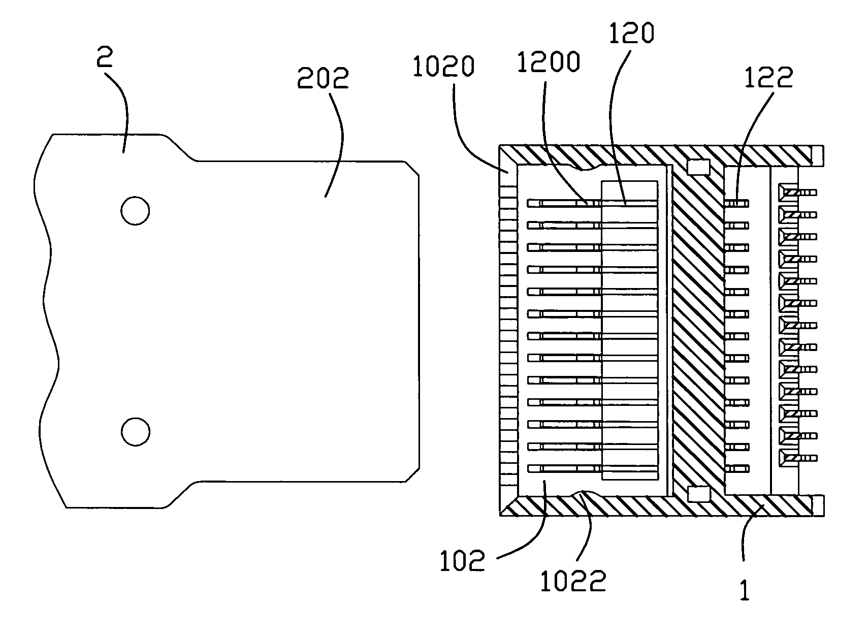
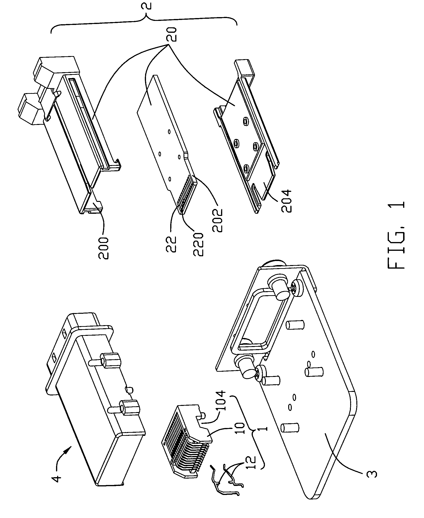
[0019]Referring to FIGS. 1-5, the present invention illustrated. A female electrical connector 1 comprises a dielectric housing 10 and a plurality of conductive contacts 12. The dielectric housing 10 defines a receiving slot 102 and a recess 104 spaced from the receiving slot 102. The receiving slot 102 comprises opposite upper inner wall (not labeled) and lower inner wall (not labeled), a pair of opposite side inner walls (not labeled) respectively intersecting the upper inner wall (not labeled) and lower inner wall (not labeled), and a pair of fulcrums 1022 respectively defined on the pair of side inner walls (not labeled). The fulcrums 1022 have curved shape with an axis perpendicular to the upper inner wall (not labeled), the width between the pair of fulcrums 1022 is shorter than the width of other position of the pair of side inner walls (not labeled). The receiving slot 102 defining a guiding mouth 1020 having a shape that the outer the position is the wider the width of the ...

second embodiment

[0026]In the present invention, the male electrical connector 2′ defines a pair of fulcrums 2022′, even the inserting direction pivoted an angle from the definite direction, the tongue board 202′ can pivot on the fulcrums, and the position of the tongue board 202′ can be restricted within narrow range by limits of the fulcrums 2022′. So the conductive contacts 12′ of the female electrical connector 1′ are restricted to electrically connect with the conductive contacts (not shown) of the male electrical connector 2′ at a position in a certain narrow range, and a proper large tolerance is accept under this situation, the manufacture of the electrical connectors 1′, 2′ and cage (not shown) is easy to be done, the assembly of the female electrical connectors 1′ and the cage (not shown) with the printed circuit board (not shown) is also easy to be done. To sum up, the combined efficiency of establish electrical connection between the electrical connectors 1′, 2′ and the printed circuit b...


PUM


Abstract

An electrical connector comprises a dielectric housing and a plurality of conductive contacts. The dielectric housing defines a receiving slot comprising opposite upper inner wall and lower inner wall, a pair of opposite side inner walls respectively intersecting the upper inner wall and lower inner wall, and a pair of fulcrums respectively defined on the pair of side inner walls. The plurality of conductive contacts is disposed in the dielectric housing with a contacting portion extending into the receiving slot from the upper wall or lower wall and disposed along a common line. Wherein, the fulcrums are disposed at the nearest places to the common line on the side inner walls.

Description

BACKGROUND OF THE INVENTION[0001]1. Field of the Invention[0002]The present invention is generally related to the art of electrical connector and more particularly to an electrical connector having fulcrums on its engaging portion for ensuring proper connection with a complementary electrical connector even engage the complementary electrical connector along an inaccurate direction rotate a certain angle from the definite coupling direction.[0003]2. Description of Related Art[0004]Low profile connectors, such as those used in SFP (Small Form Factor Pluggable) and SFP-like applications are desired in electronic devices in which space is a premium and thus it is difficult to control the impedance by modifying the spacing and size of the terminals in a reduced-size connector housing. When the terminals are modified, it becomes difficult to retain all of the mechanical functions of the connector, such as terminal retention and engagement while tuning the impedance of the connector. It i...

Claims


Application Information

Patent Timeline
Patent Type & Authority Patents(United States)
IPC IPC(8): H01R24/00
CPCH01R13/6658H01R13/748H01R12/725
Inventor HUANG, LINHSIAO, YU-SAN
Owner HON HAI PRECISION IND CO LTD
Why Eureka
Try Eureka