

Control of Impedance of RF Delivery Path
A radio frequency and path technology, applied in the direction of circuits, discharge tubes, electrical components, etc., can solve problems such as uneven etching and reduced wafer output
- Summary
- Abstract
- Description
- Claims
- Application Information
AI Technical Summary
Problems solved by technology
Method used
Image

Examples
Embodiment Construction
[0033] The following embodiments describe systems and methods for controlling the impedance of a radio frequency (RF) delivery path. It will be apparent that embodiments of the invention may be practiced without some or all of these specific details. In other instances, well known method operations have not been described in detail in order not to unnecessarily obscure the embodiments of the invention.
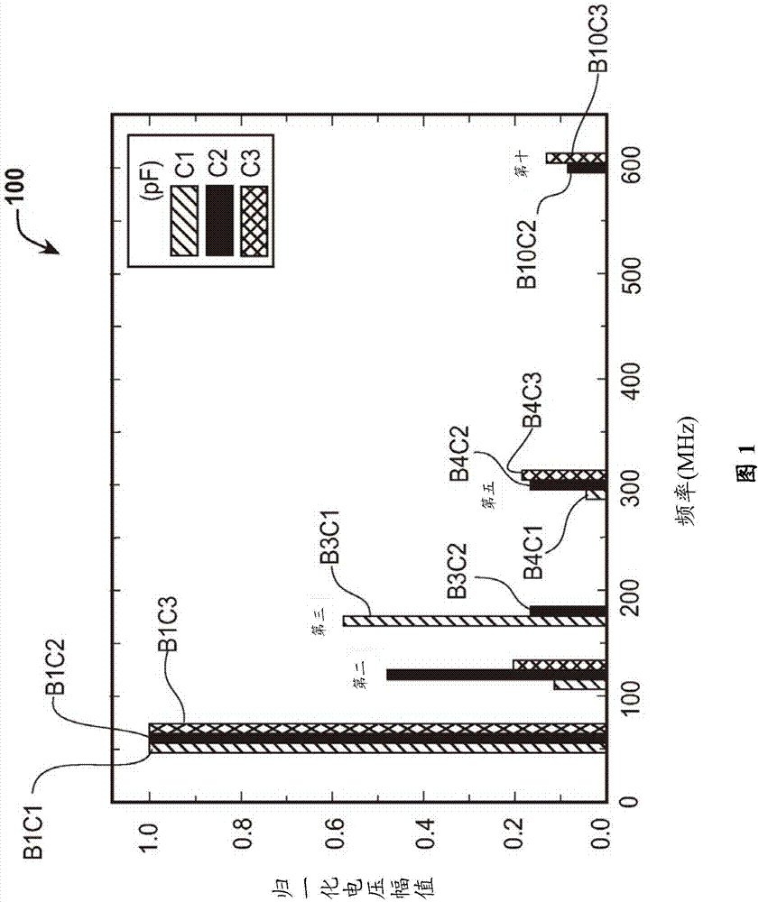
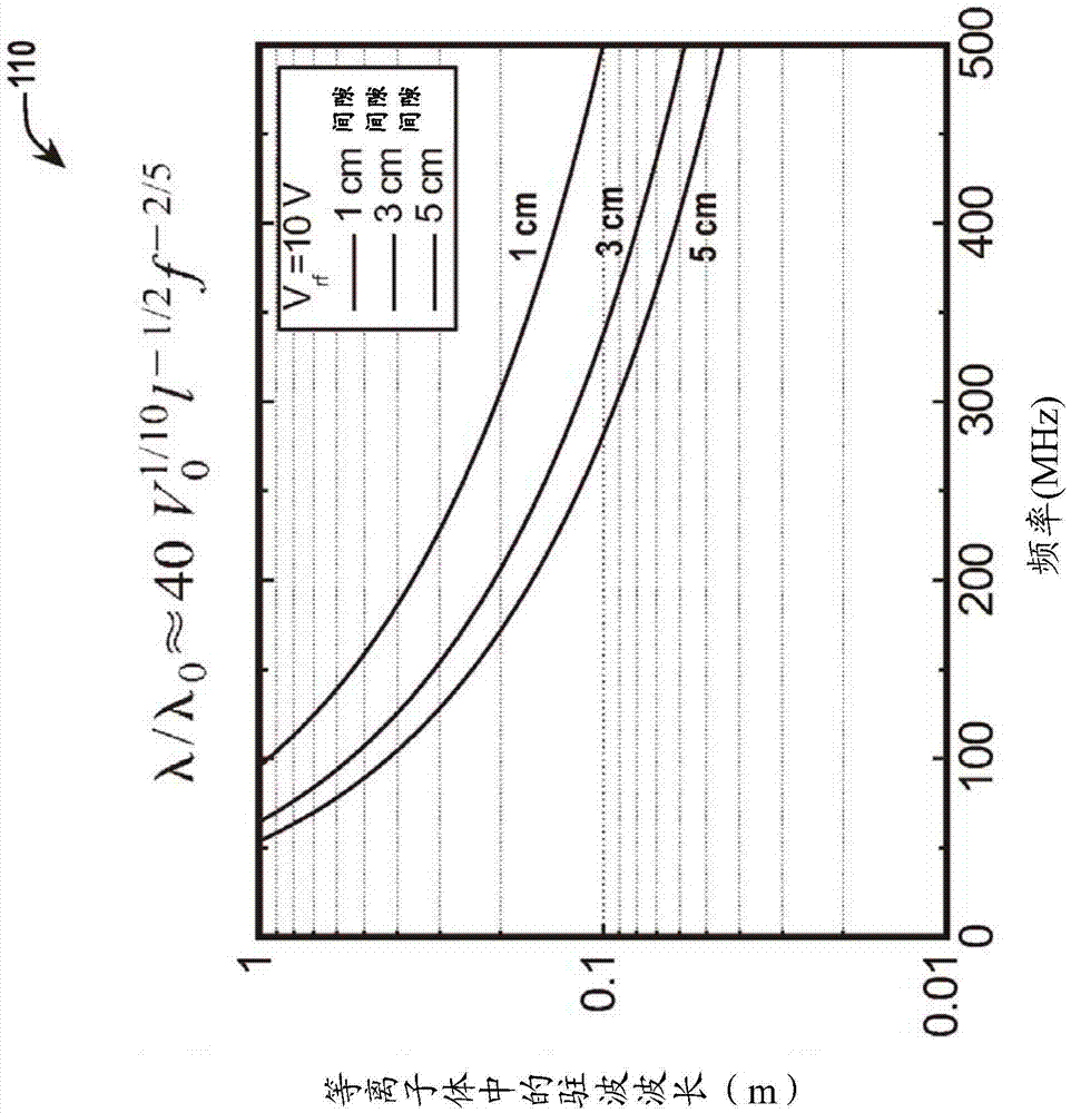
[0034] figure 1 is an embodiment of a graph 100 for illustrating the inhomogeneity of the normalized voltage in the higher order harmonics of a 60 MHz signal. The higher order harmonics create a standing wave voltage in the plasma, and the standing wave voltage causes non-uniformity in etching the substrate or depositing material on the substrate.
[0035] In various embodiments, the higher order harmonics are third or higher order harmonics. In some embodiments, the higher order harmonics are second or higher order harmonics.
[0036]Graph 100 illustrates a graph of the n...
PUM
 Abstract
Description
Claims
Application Information