Air blower with horizontal air outlet

a technology of air blower and air outlet, which is applied in the direction of lighting and heating apparatus, ventilation systems, heating types, etc., can solve the problems of limiting the height of the improved air blower device, increasing the stability, and limiting the impedance of visual inspection of the mounting surface around the air blower devi

Inactive Publication Date: 2005-04-28
LASKO HLDG
View PDF14 Cites 11 Cited by
  • Summary
  • Abstract
  • Description
  • Claims
  • Application Information

AI Technical Summary

Benefits of technology

[0008] The present invention provides an air blower device that overcomes one or more of the shortcomings of the prior art. Described is an exemplary air blower device for use on a mounting surface (desk or table top) that allows the air stream to be distributed along a path parallel with the mounting surface minimizing the disturbance to object on the mounting surface. The air blower device would ideally have an air outlet with a horizontal aspect ratio.
[0009] The height of the improved air blower device would be limited to increase the stability and limit the impedance of visual inspection of the mounting surface around the air blower device. The location of the motor within the device would be low with respect to the mounting surface resulting in a lower center of gravity of the device, thus enhancing it's stability. The movement of the fan blade of the improved air blower device would also be substantially hidden from view so as to reduce it's distractive qualities.
[0010] The improved air blower device would also have the ability to allow a user to direct the air stream where desired. Preferably the improved air blower device would be fully assembled while requiring a shipping package that will promote efficient transportation. The present invention is an improved air blower device that combines one or more of these characteristics and advantages for the user and the manufacturer.
[0017] According to another aspect of the invention, the air director housing is able to rotate about the axis of rotation within the pre-determined range of rotation substantially unimpeded by the base.

Problems solved by technology

The height of the improved air blower device would be limited to increase the stability and limit the impedance of visual inspection of the mounting surface around the air blower device.

Method used


Image

  • Air blower with horizontal air outlet
  • Air blower with horizontal air outlet
  • Air blower with horizontal air outlet

Examples


Embodiment Construction

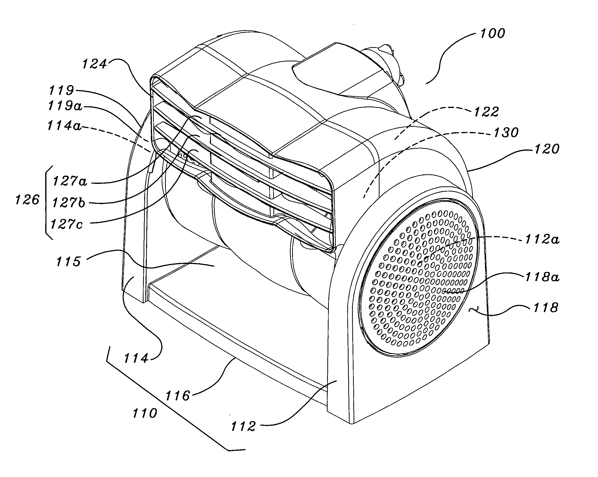
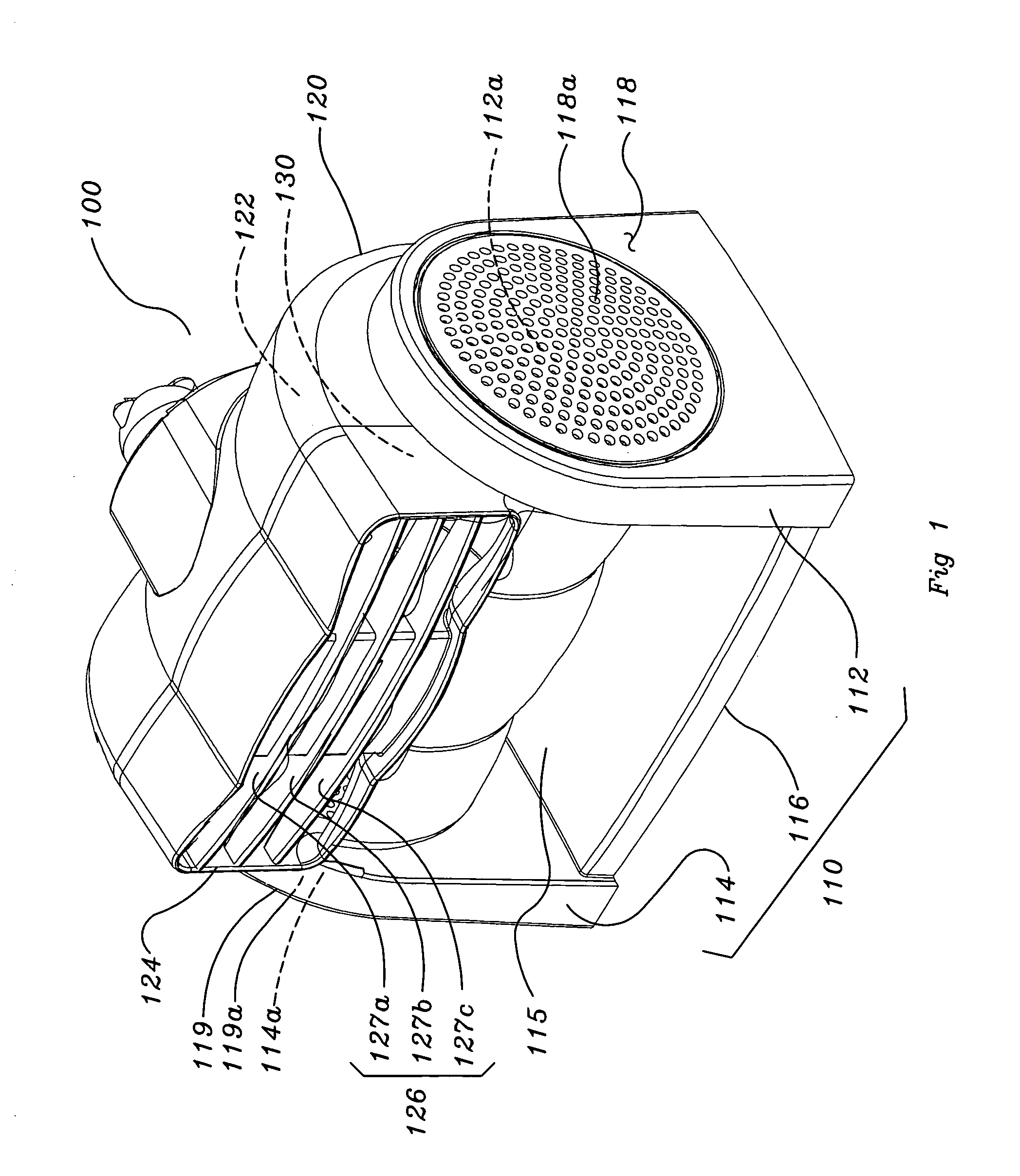
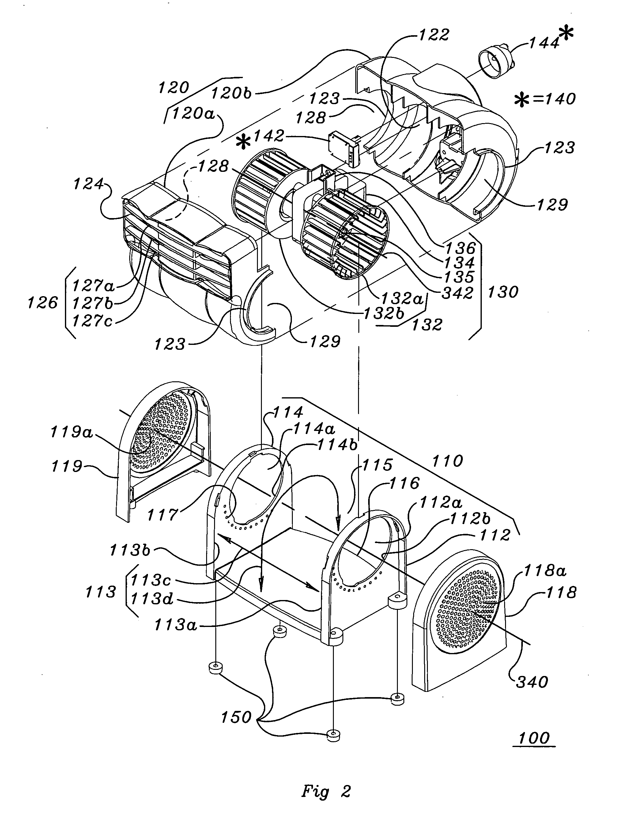
[0052] The following is a description of a portable, free standing air blower. Portable being defined as having the ability to be carried or moved with ease. Free standing being defined as having the ability to remain stable and upright without external restraints. The portable air blower has an air outlet with a horizontal aspect ratio. Also described is a limited height of the portable air blower which increases the stability and decreases it's impedance to visual inspection of a mounting surface. The motor of the device is located low with respect to the mounting surface thus lowering the center of gravity and further increasing the stability of the device. The impeller of the portable air blower is substantially hidden within the structure of the device so as to reduce the visual distractive qualities of the rotation of the impeller. Also described are various rotational features that allow the user to direct the air stream to a desired location. The overall dimensions of the po...


PUM


Abstract

A portable, free standing air blower capable of generating a user directed exhaust air stream is provided. The device includes an air blower assembly located within an air director housing rotatably coupled to a base about a horizontal axis of rotation. The air blower device includes a pre-determined range of rotation of the air director housing around the axis of rotation and the air director housing is able to rotate about the axis of rotation within the pre-determined range of rotation substantially unimpeded by the base. Preferably, the at least one air outlet can be positioned so as to direct a flow of exhaust air at an angle below an imaginary plane through the air outlet and parallel to the support surface.

Description

CROSS-REFERENCE APPLICATIONS [0001] This application is a Continuation-in-Part of application Ser. No. 10 / 236,265 filed Sep. 5, 2002.FIELD OF THE INVENTION [0002] This invention relates generally to air circulation devices for use in a household, office, or work area environment. More specifically, the present invention relates to an air circulation device having an air director housing that pivots with respect to a support surface about a horizontal axis of rotation. BACKGROUND OF THE INVENTION [0003] Various air movement devices have been utilized to generate an air stream. Many of these devices have been used to specifically create an air stream for the purpose of cooling a user. [0004] The normal use of a conventional device is to provide a cooling sensation to the user by passing a current of air generated by the air moving device over the skin of an individual. The current of air that passes over an individual serves to cool the user by increasing the convective heat loss of t...

Claims


Application Information

Patent Timeline
Patent Type & Authority Applications(United States)
IPC IPC(8): F04D25/08F24F7/007
CPCF04D25/08F24F2221/12F24F7/007
Inventor BOOHAR, ROBERT L.DOOLEY, THOMAS J.MUCHNIK, ANATOLYWILSON, RODNEY
Owner LASKO HLDG
Why Eureka
Try Eureka