Smart card connector comprising landing contacts and a cover spring as a card stopper

a technology of landing contacts and card stoppers, which is applied in the direction of sensing record carriers, two-part coupling devices, instruments, etc., can solve the problems of deterioration of contacts, small number of insert cycles, and different problems, and achieve the effect of safe pressing the reading contacts

Inactive Publication Date: 2011-02-22
AMPHENOL TUCHEL ELECTRONICS
View PDF10 Cites 4 Cited by
  • Summary
  • Abstract
  • Description
  • Claims
  • Application Information

AI Technical Summary

Benefits of technology

[0019]So as to make it possible to safely press the reading contacts into the contact support, the reading contacts are provided preferably in their mounting sections with harpoon-like projections.
[0020]Because the metal cover abuts in a resilient condition onto the upper surface of the contact support, the metal cover will act as a brake at the time the smart card is inserted. This breaking effect makes it impossible that the smart card is ejected out of the smart card connector by means of the reset springs of the sliding element. Alternatively, the metal cover can be biased or moved by its resiliency towards the card support surfaces such, that the metal cover is spaced from the card abutment or support surfaces by a distance which is smaller than the thickness of the card.
[0021]The invention provides a smart card connector which features reading contacts which will land on the contact surfaces of the smart card without creating an ejection component. Preferably, the metal cover serves as card brake and causes a reduction of tolerances or a balance of tolerance.

Problems solved by technology

With such known smart card connectors, different problems occur.
For example, if a smart card conector is frequently used, deteriorations of the contacts occur, a situation which has as a consequence, that the number of insert cycles is small.
A further problem of smart card connectors of the known design is that if inserting the smart card into the smart card reader scratches will occur which are caused by the contact elements of the smart card connectors on the contact surfaces or contact pads of the smart card.
Another problem with smart card connectors is the low safety against intrusions.

Method used


Image

  • Smart card connector comprising landing contacts and a cover spring as a card stopper
  • Smart card connector comprising landing contacts and a cover spring as a card stopper
  • Smart card connector comprising landing contacts and a cover spring as a card stopper

Examples


Embodiment Construction

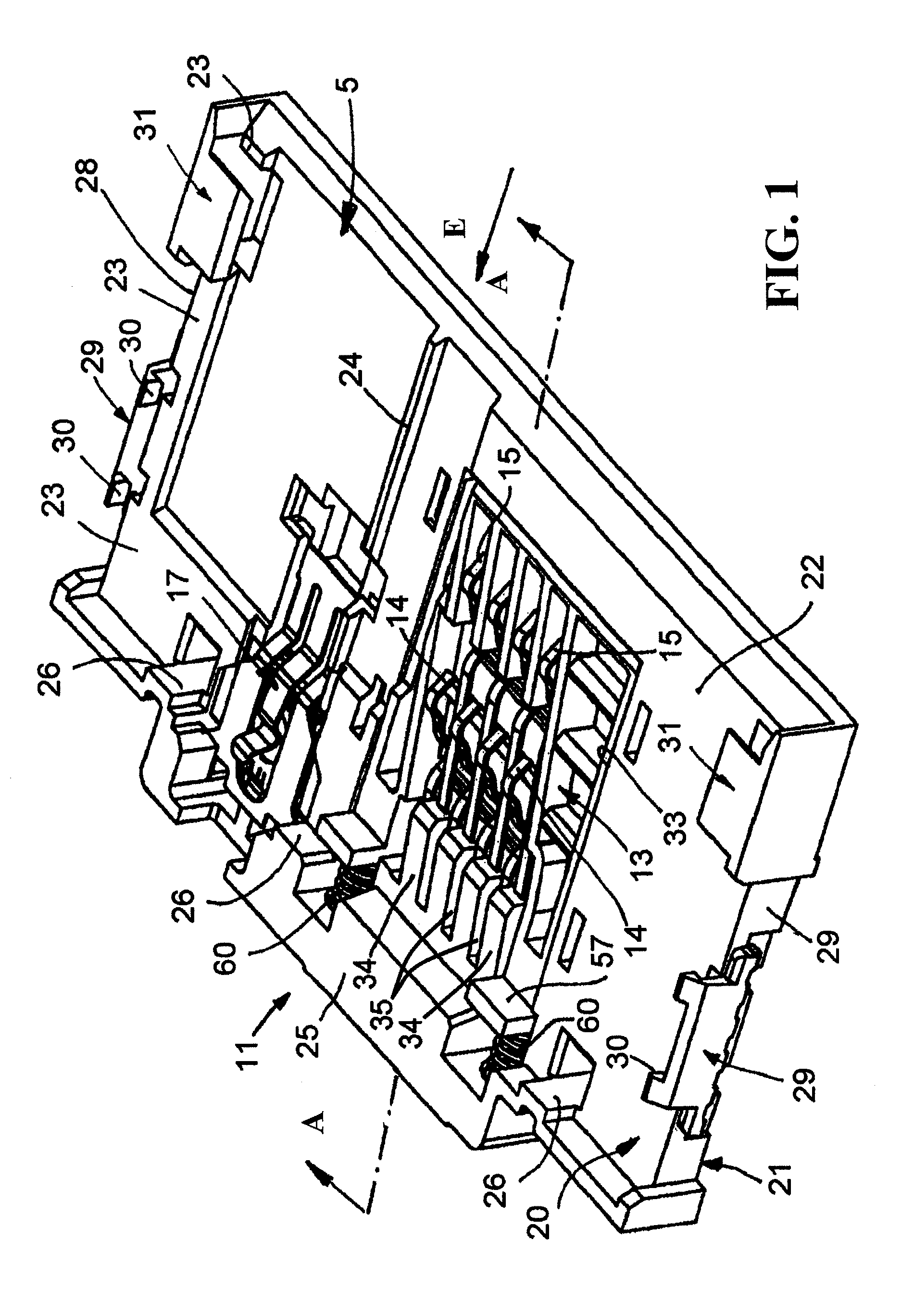
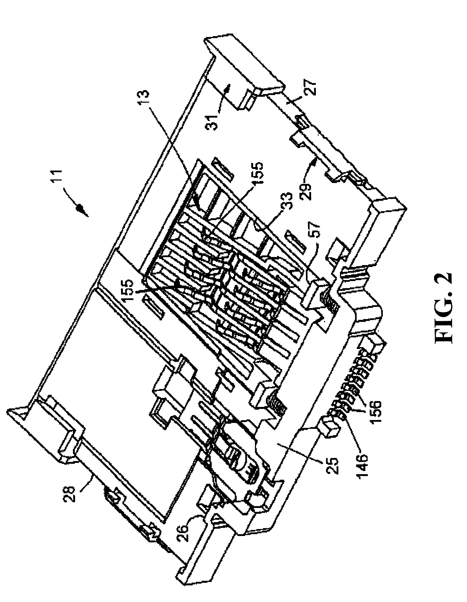
[0034]In particular FIGS. 1, 2 and 4 disclose a contact support or insulating body 11 designed in accordance with the invention, Together with a cover 12 shown in FIG. 6 the contact support 11 preferably forms the smart card connector 10 as shown in FIG. 6.

[0035]A sliding element 13 as shown in detail in FIG. 5 is reciprocally mounted within the contact support 11. In the contact support 11 reading contact elements 14, are mounted. In the following, the reading contact elements will be called reading contacts 14, 15. A group of short reading contacts 14 and a group of long reading contacts 15 is provided.

[0036]Moreover, an end position switch 17 is provided in the contact support 11. The end position switch 17 is activated by the smart card when it reaches its reading position. The smart card will be referred to below simply as the “card”.

[0037]The Contact Support 11:

[0038]The contact support 11 comprises an upper surface shown in FIGS. 1 and 2 and a bottom surface 21 shown in FIG. ...


PUM


Abstract

A smart card connector adapted to receive and place a smart card in a reading position is disclosed. The smart card connector comprises a contact support; a plurality of reading contacts attached to the contact support at a terminating end thereof, each of the reading contacts comprising a contact bulge for contacting a contact pad of the smart card and at least one control bulge for pivoting the contact bulge into contact with the contact pad of the smart card; a sliding element slidably mounted in the contact support so as to be movable between an initial position and an end position, the sliding element comprising a contact actuating member that engages the at least one control bulge as the sliding element moves toward the end position and presses the contact bulge against the contact pad of the smart card as the smart card reaches its reading position.

Description

[0001]This application is a National Phase of PCT / EP2006 / 012396 filed 21 Dec. 2006, which claims priority to DE 10 2005 061 641.0 filed 22 Dec. 2005, which is hereby incorporated by reference.FIELD OF THE INVENTION[0002]The present invention relates to a smart card connector having a contact support within which contact elements are arranged. Said contact elements will contact the contact pads of a smart card at the time the smart card (or chip card, in the following short “card”) is inserted into the smart card connector.BACKGROUND OF THE INVENTION[0003]Smart card connectors with contact elements that contact the contact pads of a smart card at the time the smart card is inserted into the smart card connector are well known. By way of example., attention is drawn to the following documents:[0004]DE 101 29580[0005]DE 3931 508[0006]GB 2198 595[0007]With such known smart card connectors, different problems occur. For example, if a smart card conector is frequently used, deteriorations...

Claims


Application Information

Patent Timeline
Patent Type & Authority Patents(United States)
IPC IPC(8): H01R24/00
CPCG06K7/0021G06K7/0026
Inventor MAITERTH, EDUARDKERNER, MANFRED
Owner AMPHENOL TUCHEL ELECTRONICS
Why Eureka
Try Eureka