
Structural improvement for stretching exercise apparatus

a technology of stretching exercise and apparatus, which is applied in the direction of sport apparatus, gymnastics exercise, stilts, etc., can solve the problems of improper repositioning of foot pedals toward a single side of the bottom, the defect of difficultly inserting the blocking rack into the regulation hole under tightening conditions, and the inability to overcome the problem of foregoing sliding fitness equipmen

Inactive Publication Date: 2011-02-22
TENG JU CHUAN
View PDF41 Cites 24 Cited by
  • Summary
  • Abstract
  • Description
  • Claims
  • Application Information

AI Technical Summary

Benefits of technology

Enables easy carrying, reduces noise and obstruction, ensures proper pedal positioning, and enhances user safety by providing a buffer effect and adjustable stroke distance, preventing injuries during exercises.

Problems solved by technology

However, the foregoing sliding fitness equipment has some problems that need to be overcome.
Although many regulation holes disposed to relative outer ends of the bottom plate can be passed by the blocking rack, the defect of difficultly inserting the blocking rack into the regulation holes under tightening condition may happen.
The blocking rack may be loosened under loosening condition and result in noise while touching the blocking rack.
Consequently, while performing expansion or drawing close to each other, the foot pedals may be improperly shifted toward a single side of the bottom plate due to non-uniform applied force and subsequent exercises are impeded.
When the flexible ropes generate elastic fatigue, the flexible ropes may easily fall into the rails to form the obstruction that the rollers disposed to the bottom portion of the foot pedals may not smoothly pass through during stretching and retracting processes.
The user may easily fall from the fitness equipment to suffer injuries.

Method used


Image

  • Structural improvement for stretching exercise apparatus
  • Structural improvement for stretching exercise apparatus
  • Structural improvement for stretching exercise apparatus

Examples


Embodiment Construction

[0022]Other features and advantages of the present invention will become apparent from the following description of the invention which refers to the accompanying drawings.

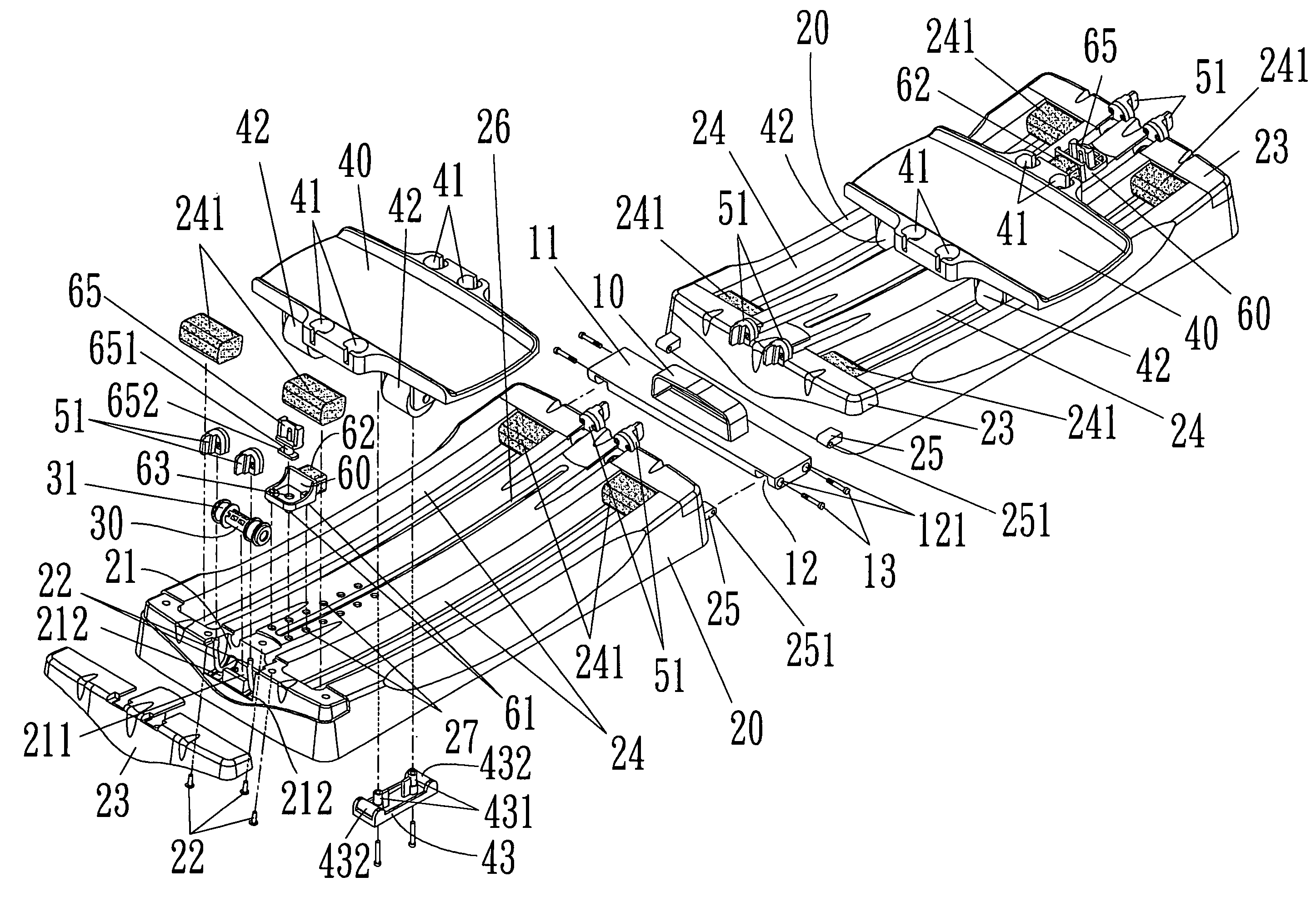
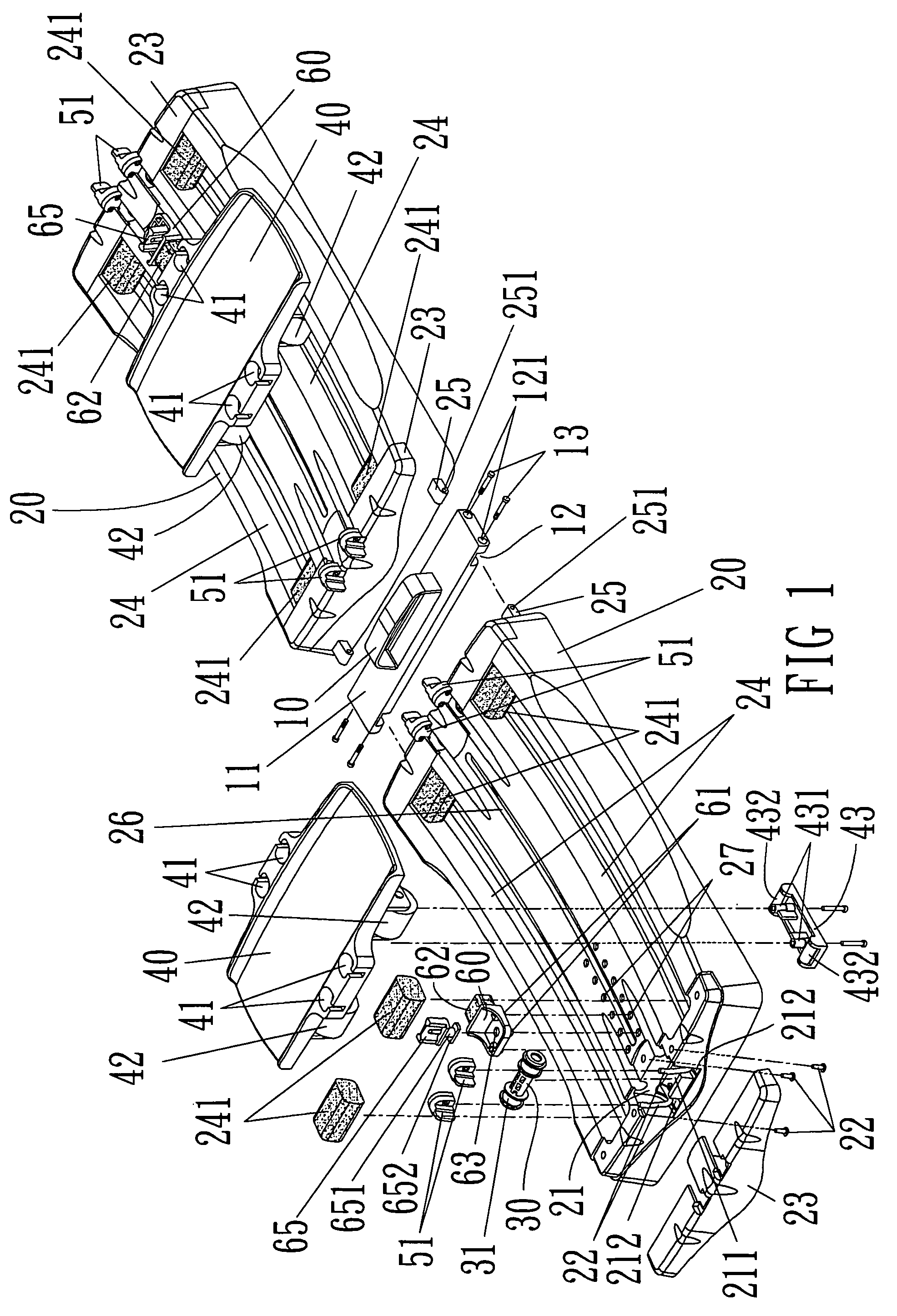
[0023]Please refer to FIG. 1 to FIG. 9, a structural improvement for stretching exercise apparatus comprises a carry handle 10, two long bottom seats 20, a plurality of roller sets 30, two pedals 40, a plurality of flexible riggings 50 and two limit seats 60.

[0024]The carry handle 10 has a pivot seat 11 formed at a bottom portion of the carry handle 10. Symmetric cross notches 12 where openings are outward are disposed to two sides of the pivot seat 11. Symmetric pivot holes 121 are disposed to two sides of each cross notch 12 to respectively pivot and connect symmetric convex ears 25 of corresponding ends of the two long bottom seats 20 at two sides of the pivot seat 11 by incorporating with axle rods 13.

[0025]Symmetric containing notches 21 where openings are upward are disposed to a central position of two shor...


PUM


Abstract

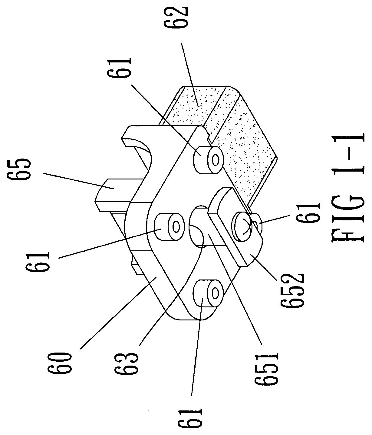
A structural improvement for stretching exercise apparatus comprises a carry handle pivotally connected symmetric long bottom seats, upper surfaces of the long bottom seats having symmetric guiding slots near two long side edges; at least two sets of symmetric casters, disposed to bottom portions of two pedals, for fitting the symmetric guiding slots; and two flexible riggings disposed inside the two long bottom seats. The feature of the apparatus is that a long channel is disposed between the symmetric guiding slots and upper surfaces of the symmetric long bottom seats. A plurality of symmetric positioning circular holes is disposed to two sides of the long channel. A limit seat has four end angles equipped with cylinders. Accordingly, the distance variations generated by the pedal relatively moving within the guiding slot can be changed by regulating the cylinders of the limit seat inserted into the positioning circular holes at different positions.

Description

FIELD OF THE INVENTION[0001]The invention relates to a structural improvement for stretching exercise apparatus that provides two feet of a user respectively standing on symmetric pedals and then configures the symmetric pedals based upon self demands of the user to achieve the goal of exercising leg functions of the user thorough resistance forces generated by outwardly unfolding or inwardly folding the pedals at the same time.BACKGROUND OF THE INVENTION[0002]A conventional exercise structure, entitled as “Multifunctional sliding fitness equipment”, includes a bottom plate taken as a main body. Sliding rails are formed on the bottom plate. A pair of foot pedals having casters is crossed over the rails of the bottom plate. The characteristics of the exercise structure are that: the bottom plate is butted with two long strip plates and connected with a hinge. The hinge toggle joint disposed to other surfaces of the two long strip plates are passed by a flexible rope. A hanging ring i...

Claims


Application Information

Patent Timeline
Patent Type & Authority Patents(United States)
IPC IPC(8): A63B23/08
CPCA63B23/03541A63B23/0488A63B21/0428A63B21/0552A63B21/0557A63B22/203A63B2071/0072A63B2022/003A63B22/205
Inventor TENG, JU-CHUAN
Owner TENG JU CHUAN
Learn More