Flexible electronic circuits and displays including a backplane comprising a patterned metal foil having a plurality of apertures extending therethrough

a technology of electronic circuits and metal foils, applied in non-linear optics, instruments, optics, etc., can solve the problems of insufficient service life of these displays, stainless steel and similar metal foils have the disadvantage of being substantially denser than other potential substrate materials, and prevent their widespread us

Inactive Publication Date: 2011-02-22
E INK CORPORATION
View PDF365 Cites 146 Cited by
  • Summary
  • Abstract
  • Description
  • Claims
  • Application Information

AI Technical Summary

Benefits of technology

[0029]In another aspect, this invention provides a process for driving a backplane comprising a conductive layer, an insulating layer and at least one transistor disposed on the opposed side of the insulating layer from the conductive layer, the process comprising varying the voltage applied to the gate of the transistor and thereby switching

Problems solved by technology

Nevertheless, problems with the long-term image quality of these displays have prevented their widespread usage.
For example, particles that make up electrophoretic displays tend to settle, resulting in inadequate service-life for these displays.
However, stainless steel and similar metal foils do have the disadvantage that they are substantially denser than other potential substrate materials such as plastics.
It has been found that, if one attempts to form an encapsulated electrophoretic display on a curved surface by coating a layer of electrophoretic medium on a flat surface (as m

Method used


Image

  • Flexible electronic circuits and displays including a backplane comprising a patterned metal foil having a plurality of apertures extending therethrough
  • Flexible electronic circuits and displays including a backplane comprising a patterned metal foil having a plurality of apertures extending therethrough
  • Flexible electronic circuits and displays including a backplane comprising a patterned metal foil having a plurality of apertures extending therethrough

Examples


Embodiment Construction

[0062]As indicated above, the present invention has several different aspects providing improvements in backplanes for electro-optic displays, and processes for the formation of such backplanes and displays. For ease of comprehension, the various different aspects of the invention will hereinafter be described separately, but it should be understood that a single backplane or display may make use of more than one aspect of the invention; for example, the 1D-curved processes of the invention may be carried out using a patterned metal foil backplane of the invention.

Patterned Metal Foil Backplane

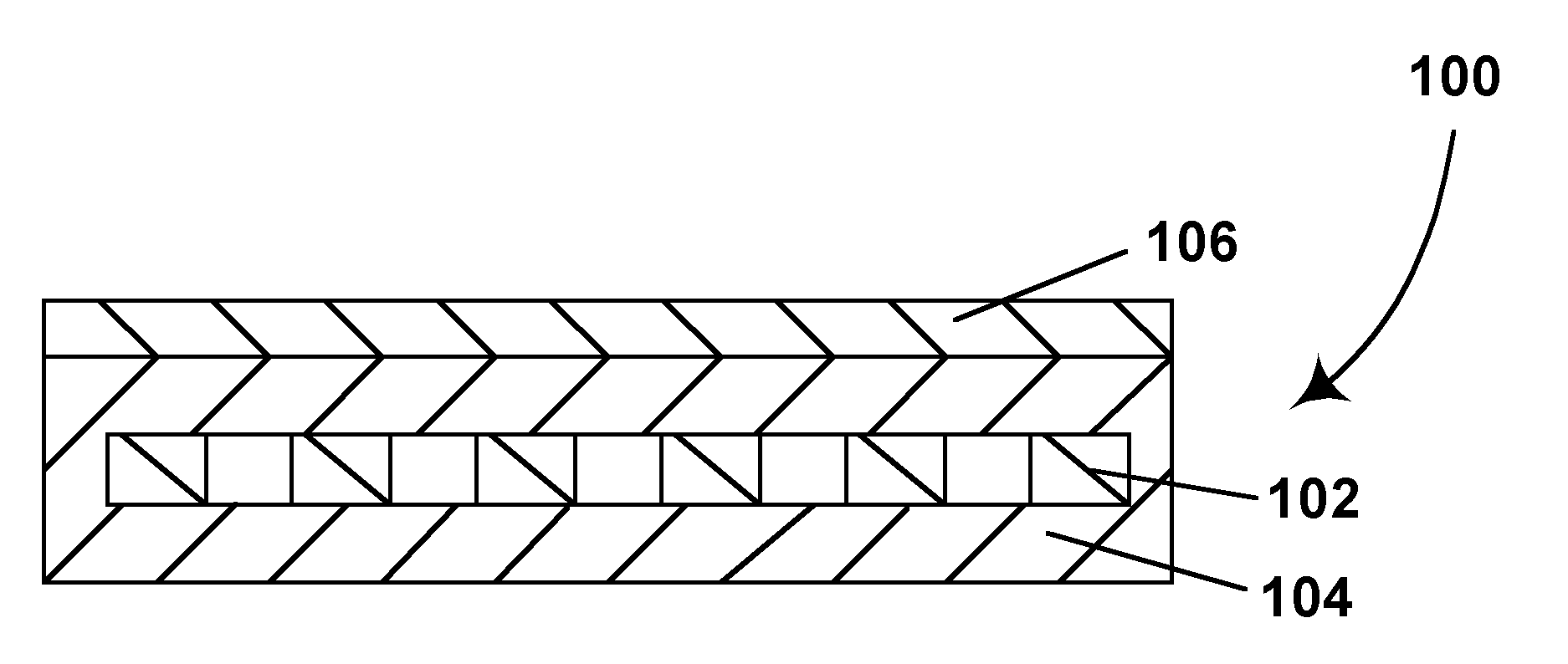
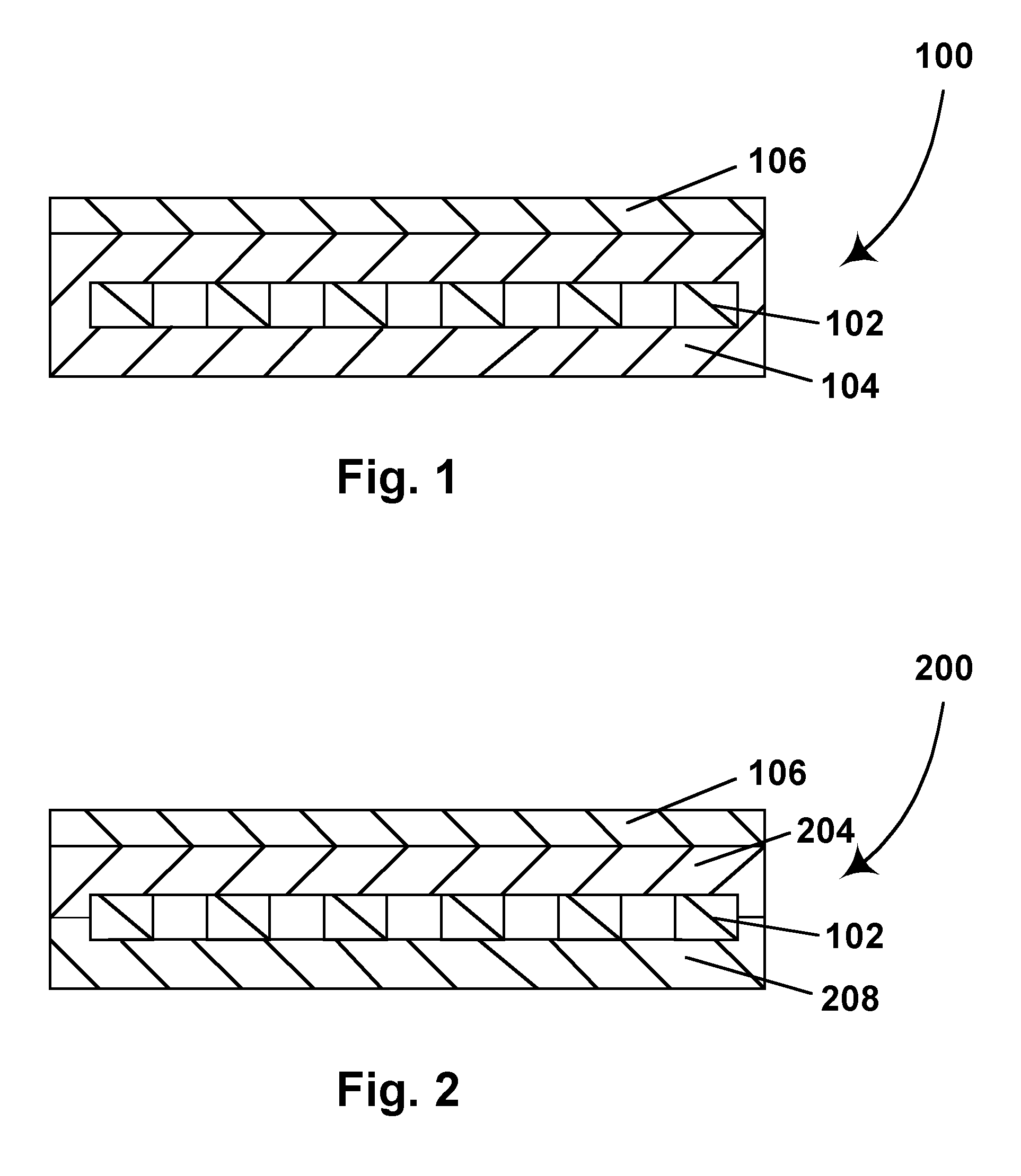
[0063]As already mentioned, in one aspect this invention provides a backplane for use in an electro-optic display, this backplane comprising a patterned metal foil coated on one or both sides with an insulating polymeric material and having a plurality of thin film electronic devices provided on the insulating polymeric material. The resulting backplane is light in weight but substantially mai...


PUM


Abstract

A backplane for use in an electro-optic display comprises a patterned metal foil having a plurality of apertures extending therethrough, coated on at least side with an insulating polymeric material and having a plurality of thin film electronic devices provided on the insulating polymeric material.

Description

CROSS REFERENCE TO RELATED APPLICATIONS[0001]This application is a continuation-in-part of application Ser. No. 09 / 836,884, filed Apr. 17, 2001 (now U.S. Pat. No. 6,825,068), and claiming benefit of Application Ser. No. 60 / 197,731, filed Apr. 18, 2000. This application also claims benefit of Application Ser. No. 60 / 319,732, filed Nov. 26, 2002 and Application Ser. No. 60 / 481,396, filed Sep. 18, 2003. The entire contents of these three applications are herein incorporated by reference. The entire contents of all U.S. patents and applications mentioned below are also herein incorporated by reference.BACKGROUND OF INVENTION[0002]This invention relates to flexible electronic circuits and displays. More specifically, this invention relates to such circuits and displays using electro-optic media. This invention also relates to production of electro-optic displays on curved surfaces; these surfaces may be curved in one or both dimensions. This invention is especially but not exclusively co...

Claims


Application Information

Patent Timeline
IPC IPC(8): H01L29/04G02F1/1333G02F1/167G02F1/16755H01L21/336H01L29/786
CPCG02F1/133305G02F1/167H01L29/78603H01L29/66765Y10T156/10G02F1/16755
Inventor KAZLAS, PETER T.AU, JOANNA F.CHEN, YUKANE, NATHAN R.COLE, DAVID JOHN
Owner E INK CORPORATION
Why Eureka
Try Eureka