Low bit rate codec

a low bit rate codec and signal technology, applied in the field of prediction encoding and decoding of signals, can solve the problems of data packet loss during transmission, inability to solve real-time applications that are delay sensitive, and inability to retransmit, so as to improve the approximation of the original signal, improve the reliability of packet loss, and improve the effect of signal prediction

Active Publication Date: 2011-02-22
GOOGLE LLC
View PDF7 Cites 34 Cited by
  • Summary
  • Abstract
  • Description
  • Claims
  • Application Information

AI Technical Summary

Benefits of technology

[0025]An advantage of the present invention is that it enables the predictive coding to be performed in such way that the coded block will be self-contained with respect to information in the excitation domain, i.e. the coded information will not be correlated with information in any previously encoded block. Consequently, at decoding, the decoding of the encoded block is based on information self-contained in the encoded block. This means that if a packet carrying an encoded block is lost during transmission, the predictive decoding of subsequent encoded blocks in subsequent received packets will not be affected by lost state information in the lost packet.
[0026]Thus, the present invention avoids the problem of error propagation that conventional predictive coding / decoding encounter during decoding when a packet carrying an encoded block is lost before reception at the decoding end. Accordingly, a codec applying the features of the present invention will become more robust to packet loss.
[0027]Preferably, the start state is chosen so as to be located in the part of the block which is associated with the highest signal power. For example, in a speech signal composed of voiced and unvoiced parts, this implies that the start state will be located well within the voiced part in a block including an unvoiced and a voiced part.
[0028]In a speech signal, high correlation exists between signal samples within a voiced part and low correlation between signal samples within an unvoiced part. The correlation in the transition region between an unvoiced part and a voiced part, and vice versa, is minor and difficult to exploit. From a perceptual point of view it is more important to achieve a good waveform matching when reproducing a voiced part of the signal, whereas the waveform matching for an unvoiced part is less important.
[0029]Conventional predictive coders operate on the signal representations in the same order as that with which the corresponding signal is produced by the signal source. Thus, any coder state representing the signal at a certain time will be correlated with previous coder states representing earlier parts of the signal. Due to the difficulties of exploiting any correlation during a transition from an unvoiced period to a voiced period, the coder states for conventional predictive coders will during the beginning of a voiced period following such a transition include information which gives a quite poor approximation of the original signal. Consequently, the regeneration of the speech signal at the decoding end will provide a perceptually degraded signal for the beginning of the voiced region.
[0030]By placing the start state well within a voiced region of a block, and then encoding / decoding the block from the start state towards the end boundaries, the present invention is able to more fully exploit the high correlation in the voiced region to the benefit for the perception. The transition from unvoiced to highly periodic voiced sound takes a few pitch periods. When placing the start state well within a voiced region of a block, the high bit rate of the start state encoding will be applied in a pitch cycle where high periodicity has been established, rather than in one of the very first pitch cycles of the voiced region.

Problems solved by technology

As packet switched networks originally were designed for transmission of non-real-time data, transmissions of real-time data over such networks causes some problems.
Data packets can be lost during transmission, as they can be deliberately discarded by the network due to congestion problems or transmission errors.
However, retransmission is not a possible solution for real-time applications that are delay sensitive.
When transferring a real-time signal as packets, the main problem with lost or delayed data packets is the introduction of distortion in the reconstructed signal.
The distortion results from the fact that signal segments conveyed by lost or delayed data packets cannot be reconstructed.
When using predictive coding in combination with packetization of the encoded signal, a lost packet will lead to error propagation since information on which the predictive coder state at the receiving end is dependent upon will be lost together with the lost packet.
This means that decoding of a subsequent packet will start with an incorrect coder state.
Thus, the error due to the lost packet will propagate during decoding and reconstruction of the signal.
However, such a reset of the coder state will lead to a degradation of the quality of the reconstructed signal.
However, not only does such a scheme require more bandwidth for transferring the encoded signal, it furthermore only reduces the effect of the lost packet.
Since the effect of a lost packet will not be completely eliminated, error propagation will still be present and result in a perceptually lower quality of the reconstructed signal.
Another problem with state of the art predictive coders is the encoding, and following reconstruction, of sudden signal transitions from a relatively very low to a much higher signal level, e.g. during a voicing onset of a speech signal.
When coding such transitions it is difficult to make the coder states reflect the sudden transition, and more important, the beginning of the voiced period following the transition.
This in turn will lead to a degraded quality of the reconstructed signal at a decoding end.

Method used


Image

  • Low bit rate codec
  • Low bit rate codec
  • Low bit rate codec

Examples


example c -

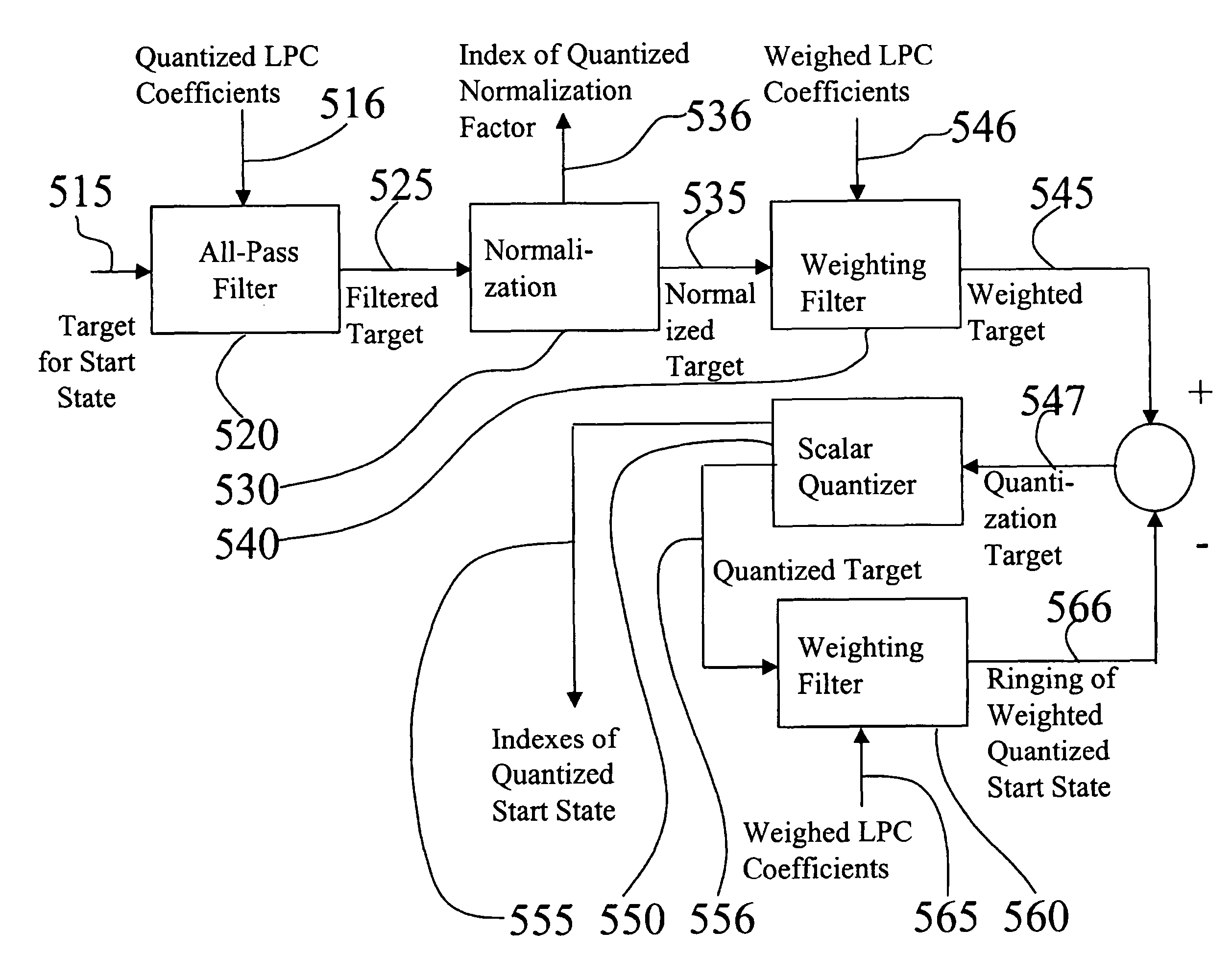
Example C-Code for the Encoding from the Start State Towards Block Boundaries

[0044]

void iLBC_encode( / * main encoder function * /     float *speech, / * (i) speech data vector * /     unsigned char *bytes, / * (o) encoded data bits * /     float *block, / * (o) decoded speech vector * /     int mode, / * (i) 1 for standard encoding 2 for redundant encoding * /     float *decresidual, / * (o) decoded residual prior to gain adaption    (useful for a redundant encoding unit) * /     float *syntdenum, / * (o) decoded synthesis filters (useful for a          redundant encoding unit) * /     float *weightnum, / * (o) weighting numerator (useful for a redundant          encoding unit) * /     float *weightdenum / * (o) weighting denumerator (useful for a           redundant encoding unit) * / ){  float data[BLOCKL];  float residual[BLOCKL], reverseResidual[BLOCKL];  float weightnum[NSUB*(FILTERORDER+1)], weightdenum[NSUB*(FILTERORDER+1)];  int start, idxForMax, idxVec[STATE_LEN];  float reverseDecresidual[BLOCKL], ...


PUM


Abstract

The present invention relates to improvements of predictive encoding / decoding operations performed on a signal which is transmitted over a packet switched network. The signal is encoded on a block by block basis in such way that a block A-B is predictive encoded independently of any preceding blocks. A start state (715) located somewhere between the end boundaries A and B of the block is encoded using any applicable coding method. Both block parts surrounding the start state is then predictive encoded based on the start state and in opposite directions with respect to each other, thereby resulting in a full encoded representation (745) of the block A-B. At the decoding end, corresponding decoding operations are performed.

Description

TECHNICAL FIELD OF THE INVENTION[0001]The present invention relates to predictive encoding and decoding of a signal, more particularly it relates to predictive encoding and decoding of a signal representing sound, such as speech, audio, or video.TECHNICAL BACKGROUND AND PRIOR ART[0002]Real-time transmissions over packet switched networks, such as speech, audio, or video over Internet Protocol based networks (mainly the Internet or Intranet networks), has become increasingly attractive due to a number of features. These features include such things as relatively low operating costs, easy integration of new services, and one network for both non-real-time and real-time data. Real-time data, typically a speech, an audio, or a video signal, in packet switched systems is converted into a digital signal, i.e. into a bitstream, which is divided in portions of suitable size in order to be transmitted in data packets over the packet switched network from a transmitter end to a receiver end.[...

Claims


Application Information

Patent Timeline
Patent Type & Authority Patents(United States)
IPC IPC(8): G10L21/04G10L19/02G10L19/04
CPCG10L19/04G10L19/0212
Inventor ANDERSEN, SOREN V.HAGEN, ROARKLEIJN, BASTIAAN
Owner GOOGLE LLC
Why Eureka
Try Eureka