Low bit rate codec

US20060153286A1Active Publication Date: 2006-07-13GOOGLE LLC

Image

  • Low bit rate codec
  • Low bit rate codec
  • Low bit rate codec

Examples


Embodiment Construction

[0040] The encoding and decoding functionality according to the invention is typically included in a codec having an encoder part and a decoder part. With reference to FIG. 1 and 2, an embodiment of the invention is shown in a system used for transmission of sound over a packet switched network.

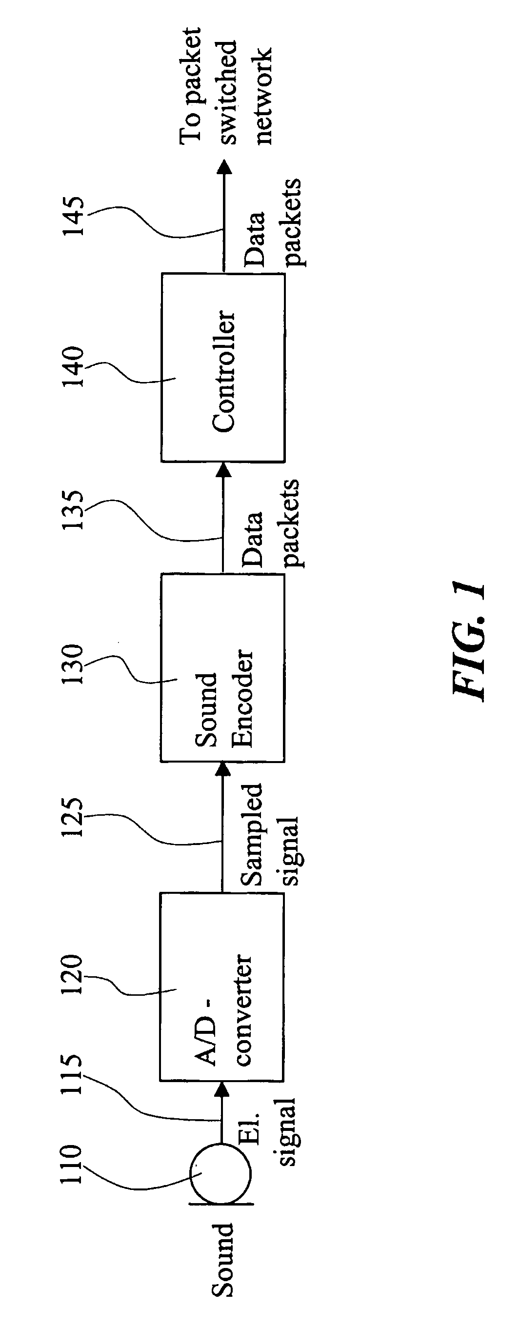
[0041] In FIG. 1 an encoder 130 operating in accordance with the present invention is included in a transmitting system. In this system the sound wave is picked up by a microphone 110 and transduced into an analog electronic signal 115. This signal is sampled and digitized by an A / D-converter 120 to result in a sampled signal 125. The sampled signal is the input to the encoder 130. The output from the encoder is data packets 135. Each data packet contains compressed information about a block of samples. The data packets are, via a controller 140, forwarded to the packet switched network.

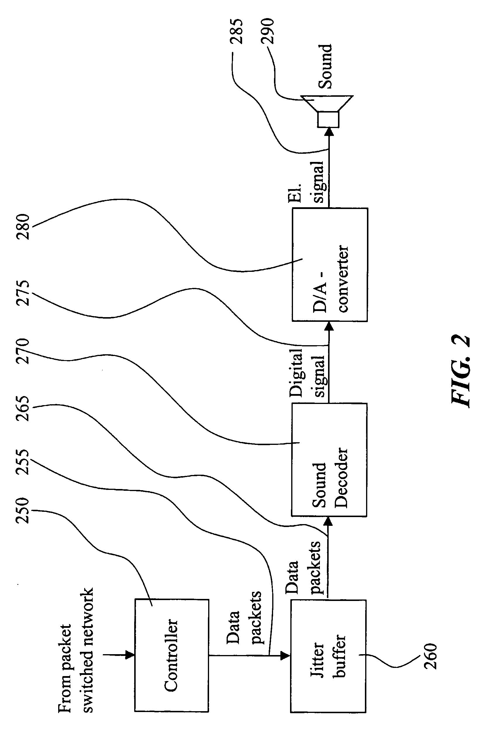
[0042] In FIG. 2 a decoder 270 operating in accordance with the present invention is included in a receiv...


PUM


Abstract

The present invention relates to improvements of predictive encoding / decoding operations performed on a signal which is transmitted over a packet switched network. The signal is encoded on a block by block basis in such way that a block A-B is predictive encoded independently of any preceding blocks. A start state (715) located somewhere between the end boundaries A and B of the block is encoded using any applicable coding method. Both block parts surrounding the start state is then predictive encoded based on the start state and in opposite directions with respect to each other, thereby resulting in a full encoded representation (745) of the block A-B. At the decoding end, corresponding decoding operations are performed.

Description

TECHNICAL FIELD OF THE INVENTION [0001] The present invention relates to predictive encoding and decoding of a signal, more particularly it relates to predictive encoding and decoding of a signal representing sound, such as speech, audio, or video. TECHNICAL BACKGROUND AND PRIOR ART [0002] Real-time transmissions over packet switched networks, such as speech, audio, or video over Internet Protocol based networks (mainly the Internet or Intranet networks), has become increasingly attractive due to a number of features. These features include such things as relatively low operating costs, easy integration of new services, and one network for both non-real-time and real-time data. Real-time data, typically a speech, an audio, or a video signal, in packet switched systems is converted into a digital signal, i.e. into a bitstream, which is divided in portions of suitable size in order to be transmitted in data packets over the packet switched network from a transmitter end to a receiver ...

Claims


Application Information

Patent Timeline
13 Jul 2006
Publication
US20060153286A1
IPC
H03H7/30; G10L19/02; G10L19/04
CPC
G10L19/04; G10L19/0212
Inventors
ANDERSEN, SOREN V.; HAGEN, ROAR