Supercharge Your Innovation With Domain-Expert AI Agents!

Windshield wiper system with a self-locking device that is active when the wiper drive is in a non-operating state

a wiper drive and self-locking technology, which is applied in the field of windshield wiper systems, can solve the problems of excessively weak self-locking of the drive, the risk of the wiper being moved for example by the head wind, etc., and achieve the effect of preventing the wiper from moving into the wiping area, and avoiding the possibility of affecting the wiper driv

Active Publication Date: 2011-03-01
ROBERT BOSCH GMBH
View PDF10 Cites 40 Cited by
  • Summary
  • Abstract
  • Description
  • Claims
  • Application Information

AI Technical Summary

Benefits of technology

The invention provides a way to implement self-locking in wiper drives without using mechanical measures. The control system monitors the position of the wiper when the drive is not in use and quickly returns the wiper to its original position when needed. This self-locking feature is especially useful when the vehicle is turned off and the driver needs to quickly wipe the windscreen. The control system is designed to preserve the vehicle battery and can wake up periodically to prevent any position changes while in standby mode. Electronic self-locking can be used in any wiper system with electronic wiper-motor actuation.

Problems solved by technology

This is desirable since the armature shaft of the wiper motor is not supplied with power in the non-operating state and therefore would rotate freely without adequate self-locking, this producing the risk of the wiper being moved into the wiping area, for example by the head wind.
One problem with this is the slight deviation of the wiper linkage from the extended position, which deviation is associated with the new inoperative position and can lead to excessively weak self-locking of the drive.
A highly desired variant of the reversing drive, the so-called direct wiper drive, is particularly problematical in terms of self-locking.
However, unconventional mechanical self-locking measures such as helical springs or blocking elements are relatively complicated and have to be matched to the respective design of the wiper system.
However, complete omission of self-locking measures is not possible either since otherwise, as already explained above, the wiper arm or the wiper arms could move from the park position into the wiping area as a result of misuse or other external influences (for example a car wash).

Method used


Image

  • Windshield wiper system with a self-locking device that is active when the wiper drive is in a non-operating state
  • Windshield wiper system with a self-locking device that is active when the wiper drive is in a non-operating state
  • Windshield wiper system with a self-locking device that is active when the wiper drive is in a non-operating state

Examples


Embodiment Construction

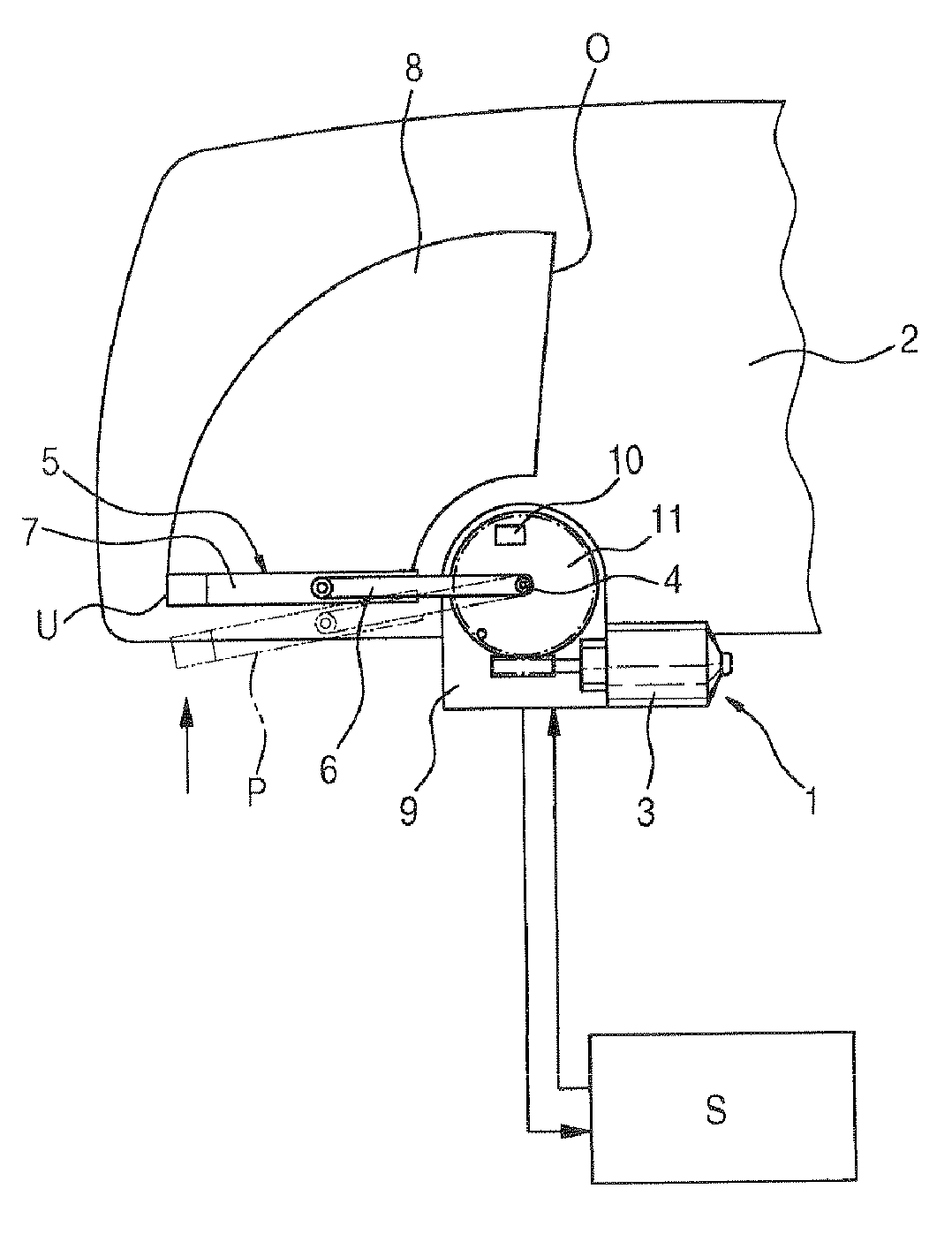
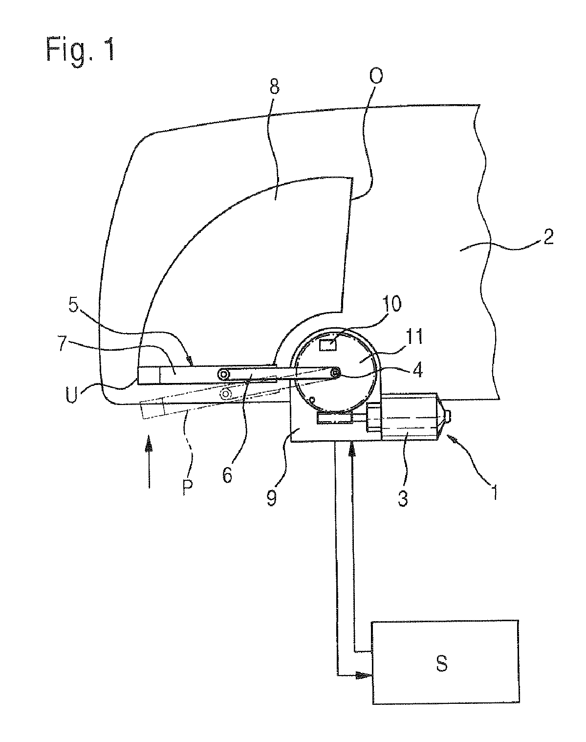
[0015]FIG. 1 shows a schematic illustration of a windshield wiper apparatus according to the invention on a windshield 2 of a motor vehicle. For reasons of clarity, only half of the windshield 2 is shown here. The wiper system comprises a drive 1 with a reversing motor 3 which drives an output shaft 4 to which a wiper 5 is connected in a rotationally fixed manner. The wiper 5 substantially comprises a wiper arm 6 which has a wiper blade 7 connected to its free end in an articulated manner. During operation, the output shaft 4 executes an oscillating movement, so that the wiper 5 moves across the windshield 2 in an oscillating manner. In this case, the region of the windshield 2 which is covered by the wiper blade 7 forms the wiping area 8.

[0016]When the reversing motor 3 is supplied with power, the wiper 5 oscillates between the lower reversal position U and an upper reversal position O. An extended park position P, in which the wiper is in the non-operating state, is also indicated...


PUM


Abstract

In order to ensure, when the drive (1) is in a non-operating state, a self-locking that counters a change in position of the wiper (5), an electronically implemented self-locking is provided. To this end, the controller (S) of the wiper system monitors the wiper (5) during the non-operating state of the drive (1) by evaluating the position sensor signals for a change in position and, in response to the position monitoring, activates the drive (1) in order to return the wiper (5) into a set position (U, P).

Description

BACKGROUND OF THE INVENTION[0001]The invention relates to a windshield wiper system for a motor vehicle, comprising at least one wiper, a drive, a self-locking device that is active when the drive is in a non-operating state and counteracts a change in position of the wiper, and comprising an electronic control means which actuates the drive and detects the input of position sensor signals of the wiper.[0002]A wiper system of this type comprising means for locking the wiper drive in the non-operating state is already known from DE 103 12 982 A1.[0003]Windshield wiper drive apparatuses in which a rotary movement of a motor which rotates in a prespecified direction is converted into a to-and-fro movement of the windshield wiper by an eccentric mechanism, in particular a crank gear, have long been known. The output shafts of such drives are therefore connected indirectly, via a crank and a thrust linkage, to the wiper shafts to which wiper arms with wiper blades are fixed. The non-unif...

Claims


Application Information

Patent Timeline
Patent Type & Authority Patents(United States)
IPC IPC(8): B60S1/08
CPCB60S1/08B60S1/0814Y10S318/02
Inventor TISCH, FLORIANKARCHER, HUBERTUS
Owner ROBERT BOSCH GMBH
Features
  • R&D
  • Intellectual Property
  • Life Sciences
  • Materials
  • Tech Scout
  • Unparalleled Data Quality
  • Higher Quality Content
  • 60% Fewer Hallucinations
Learn More