IGBT drive protection circuit

A technology for driving protection circuits and resistors, applied in electrical components, electronic switches, pulse technology, etc., can solve the problems of reliable operation of inverters and other equipment, not suitable for fault self-checking, and imperfect soft-off function.

Inactive Publication Date: 2010-03-31
SHENZHEN CLOU DRIVE TECH CO LTD
View PDF1 Cites 74 Cited by
  • Summary
  • Abstract
  • Description
  • Claims
  • Application Information

AI Technical Summary

Problems solved by technology

[0004] However, after a comprehensive analysis of the current various circuit schemes, it can be seen that the existing various circuit schemes have their own design focus, including the schemes of the above-mentioned patent applications with comprehensive protection functions, all of which have the following deficiencies: 1. There is no indication of the state of the undervoltage protection of the driving power supply, and it has not been transmitted to the control circuit, which is not suitable for the fault self-test requirements; 2. When the voltage Vce of the IGBT collector-emitter voltage Vce is too high, the protection circuit How much higher, the delay time from turn-on to turn-off is fixed, and the delay time cannot be dynamically adjusted according to the level of voltage Vce; 3. The soft-off function is not perfect
[0005] It can be seen that none of the drive circuit schemes has a very complete protection function, which will adversely affect the reliable operation of inverters and other equipment

Method used


Image

  • IGBT drive protection circuit

Examples


Embodiment Construction

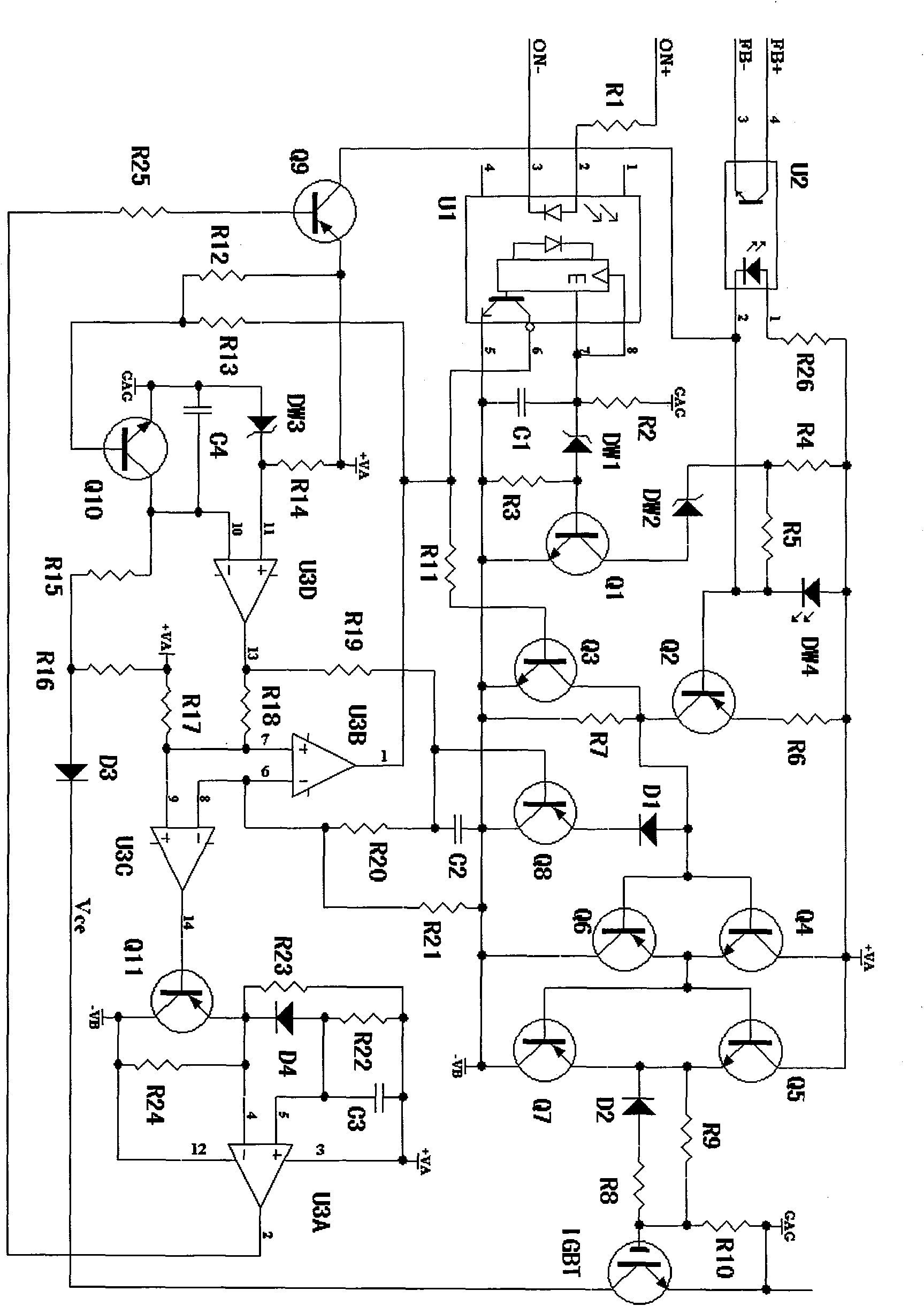
[0024] Such as figure 1 Shown, a kind of IGBT drive protection circuit of the present invention, it mainly comprises:

[0025] A positive power supply +VA, such as +18V, reference ground GAG, and a negative power supply -VB, such as -8V, are used to provide dual constant voltages;

[0026] An insulated gate bipolar transistor IGBT for controlling the on-off of the load (in order to illustrate the connection relationship between the circuit of the present invention and the IGBT, it is marked in the figure, and is not a component of the circuit of the present invention);

[0027]A signal isolation optocoupler U1, you can choose a high-speed optocoupler such as 6N137, etc., the anode series resistor R1 and cathode of the diode at the input end are respectively connected to the differential signal ON+ and ON- from the control circuit to determine the IGBT turn-on and turn-off, and the output end passes through the resistor R11 is connected to the base of a switching transistor Q3...


PUM


Abstract

The invention discloses an IGBT drive protection circuit, which comprises positive and negative power supplies, a signal and feedback optical coupler, a signal amplification circuit, an undervoltage detection and indication circuit, an IGBT overcurrent detection and reset circuit, a soft turn-off circuit, a fault latch and retaining circuit and the like. The undervoltage detection circuit if the power supply at the receiving terminal of the signal optical coupler and the positive/negative power supply are undervoltage, and an LED is lighted if the power supply at the receiving terminal of thesignal optical coupler and the positive/negative power supply are not undervoltage to enable a drive circuit. The IGBT overcurrent detection circuit can sample a collector-emitter voltage drop duringthe period when the IGBT is turned on, detect time delay according to high-low dynamic adjustment of the collector-emitter voltage drop, start a soft turn-off process and perform self locking to ensure soft turn off when the collector-emitter voltage drop exceeds a preset threshold, retain the overcurrent fault state, keep the IGBT turned off during the retaining period, transmit the state to a control circuit and keep time set between millisecond and second.

Description

technical field [0001] The present invention relates to a kind of IGBT (IGBT, English acronym of Insulated Gate Bipolar Transistor, Insulated Gate Bipolar Transistor) drive protection circuit, especially a kind of in frequency converter, switching power supply, UPS (uninterruptible power supply) etc. equipment as power The driving protection circuit of the insulated gate bipolar transistor IGBT of the switching device. Background technique [0002] At present, because the insulated gate bipolar transistor IGBT is easy to drive and can handle large current and high voltage at a high switching frequency, it is widely used as a power switch in high-power inverters, switching power supplies, UPS and other equipment at home and abroad. device, so the IGBT drive protection circuit has become an important circuit related to the reliability of the inverter and other complete machines. [0003] The IGBT driving protection circuit adopted by the existing frequency converter etc. has ...

Claims


Application Information

Patent Timeline
Patent Type & Authority Applications(China)
IPC IPC(8): H03K17/567H03K17/08
Inventor 范家闩
Owner SHENZHEN CLOU DRIVE TECH CO LTD
Why Eureka
Try Eureka