Self locking hinge

a self-locking, hinge technology, applied in the field of folding hinges, can solve the problems of inability to incorporate all the novel aspects of the prior art, complicated and costly manufacturing, internal parts, etc., and achieve the effects of convenient transportation and storage, reduced pole size, and convenient and convenient transportation

Inactive Publication Date: 2006-02-28
FULCRUM SPORTS
View PDF21 Cites 71 Cited by
  • Summary
  • Abstract
  • Description
  • Claims
  • Application Information

AI Technical Summary

Benefits of technology

[0011]One key advantage of the invention is that it can be opened and closed with one hand and with one fluid motion. In the case of a wading staff a person simply holds the upper half of the wading staff containing the handle and releases the bottom half of the wading staff. The self locking hinge automatically engages once the bottom half of the wading staff is in place, that is, lined up end to end with the top half of the wading staff (See FIG. 4 and FIG. 5). This single hand operation is desirable and convenient in many applications, and more specifically, with a fly fisherman who is generally holding a fishing rod in one hand and thus only has one hand free to manage a wading staff.
[0012]Another advantage of the invention is that it allows for a wading staff, or other pole device, to be broken down to a compact size for easy transportation and storage. This is desirable in almost all applications, especially wading staffs and canes. If needed several hinges may be placed in the pole thereby allowing the pole to be folded a number of times, further reducing the size of the pole for transport and storage.
[0013]The invention consists of essentially three pieces; two hinge portions that are pivotally joined and a self locking latch that locks the two hinge portions together. The two hinge portions are designed to be disposed end to end and are pivotally engaged with each other around a pivot pin. The hinge portions are geometrically designed so that they do not protrude beyond the pole diameter. The only exceptions are the lobe portions of the hinge that create an offset pivot point. The offset pivot point allows the poles attached to the hinge to touch and to be parallel when the entire pole is in its closed position. The third portion of the invention is the self locking latch which is spring actuated. The self locking latch is permanently attached to one hinge portion. The self locking latch locks the invention by engaging a recess or notch in the opposing hinge portion. When engaged the hinge creates a strong connection that is sufficient for its application purpose. The invention is simply unlocked by pressing down on the self locking latch.
[0014]Accordingly, one object of this invention is to provide a self locking hinge that can be easily engaged and disengaged with one hand.
[0015]Another object of this invention is to provide a self locking hinge that is simple and inexpensive to manufacture.
[0016]A third object of this invention is to provide a self locking hinge that can be incorporated with poles, or other devices, so that one may possess a poled, or other, device that is strong in nature while being capable of being broken down to a compact size for easy transport and storage.

Problems solved by technology

However, none of the prior art incorporates all of the novel aspects of the present invention of a simple, inexpensive, easy to manufacture, strong self locking hinge that most importantly can be operated with one hand.
Other devices have an internal spring loaded means, such as U.S. Pat. No. 4,736,490, but have many internal parts that make is complicated and costly to manufacture.
Furthermore, this hinge device could be disengaged if one where to apply force to underside of the hinge, a concept not desirable to wading staffs, walking sticks and canes.
This device does not create a straight 180-degree orientation and does not easily collapse down for easy storage.
All of these references suffer from the common problems of not being able to be engaged or disengaged with one hand.

Method used


Image

  • Self locking hinge
  • Self locking hinge
  • Self locking hinge

Examples


Embodiment Construction

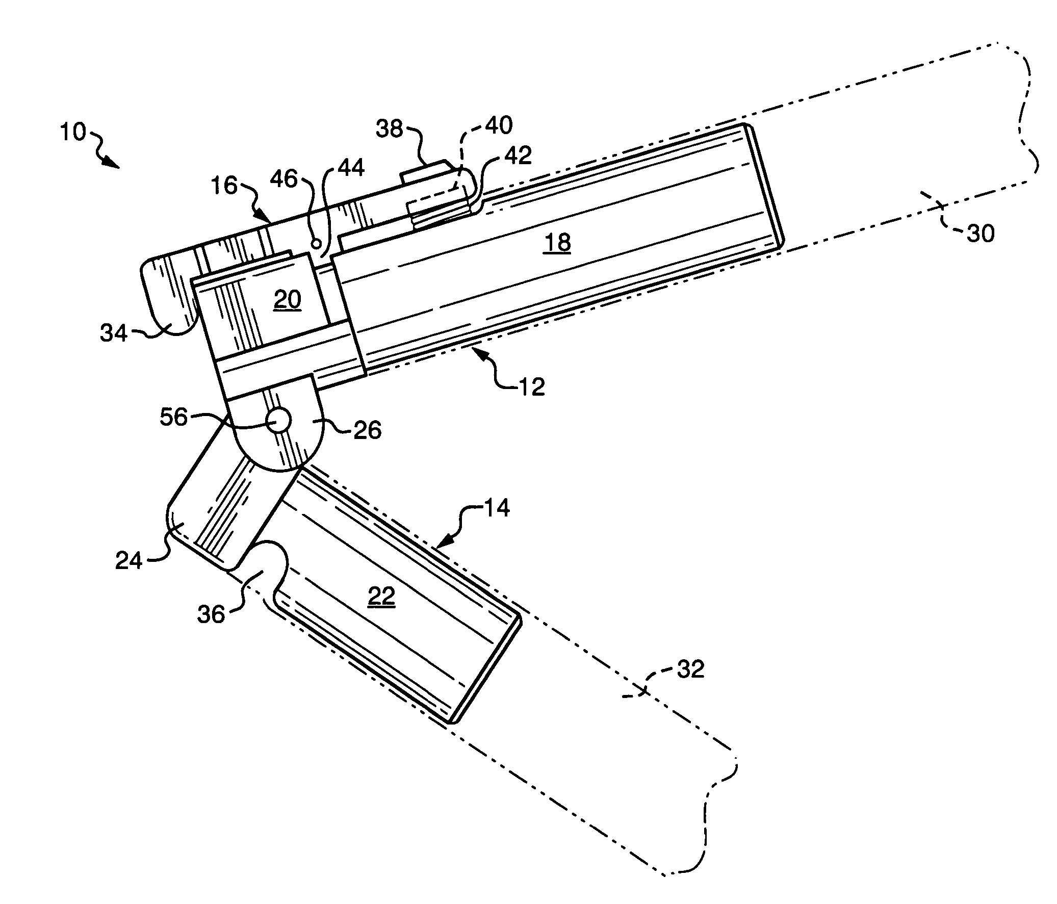
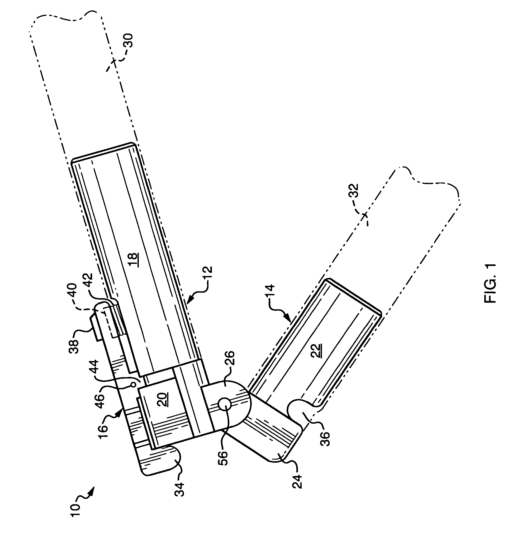
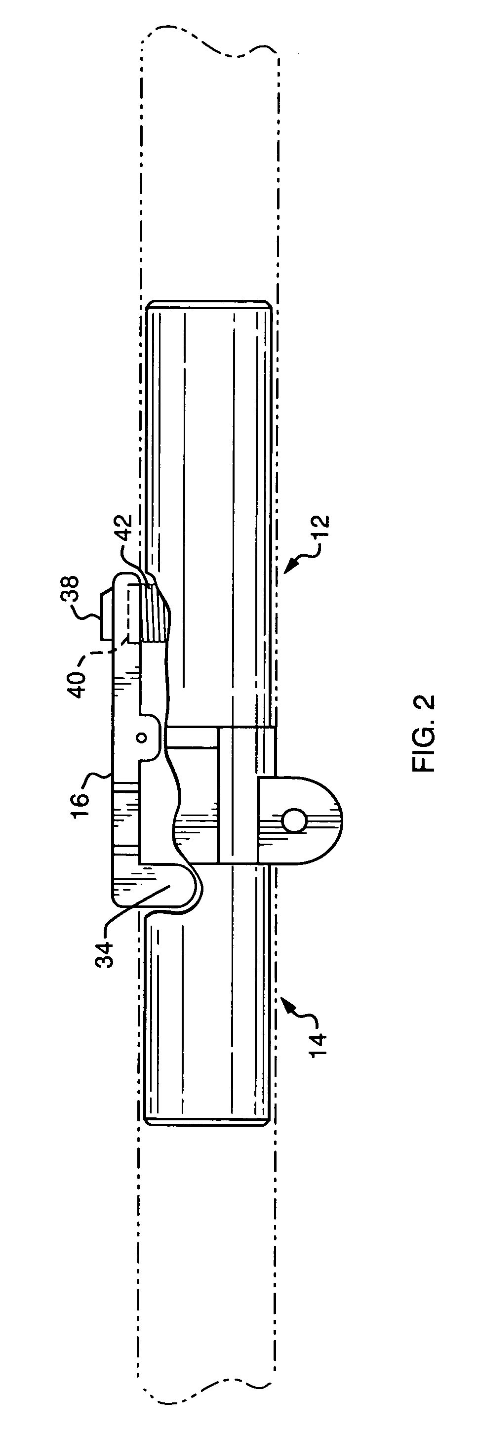
[0025]Referring to the Figures and more specifically FIG. 1 and FIG. 3, the invention 10 consists of essentially three parts, a first hinge portion 12, a second hinge portion 14 and a self locking latch 16. Each hinge portion has a main body portion and a connecting portion containing lobes designed to connect the two hinge portions. The first hinge portion 12 has a main body portion 18 and a connecting portion 20 with two lobes 26 and 54. The second hinge portion 14 has a main body portion 22 and a connecting portion 24 with a single lobe 28. The main body portions of the hinge portions are design to allow the hinge portions to be engaged with poles or other devices. In FIG. 1, the main body portion 18 of first hinge portion 12 is disposed in pole 30 while the main body portion 22 of second hinge portion 14 is disposed in pole 32. The invention 10 can be made in a variety of geometric shapes so that it can be connected with variety of different shaped poles or devices requiring the...


PUM


Abstract

The present invention is an ingenuously designed self locking hinge that is simple to manufacture and can come in a variety of shapes given the application requirements. It has few parts making it cost effect and simple to use. The hinge can easily be opened and closed with one hand while at the same time creating a strong hinge connection. The invention can be used in a number of applications, including use with poles for many common applications such as walking sticks, canes, ski poles and wading staffs used by fly fishermen who need poles to navigate through a stream to avoid holes or rocks in the stream bed. The invention can also be used in conjunction with devices that require a collapsible frame.

Description

BACKGROUND[0001]a) Field of the Invention[0002]This invention relates to the field of folding hinges designed for use in conjunction with devices that use poles or similar means and where it is desirable to collapse the same. More specifically, this device relates to devices that are used in conjunction with ski poles, canes, walking sticks, or wading staffs used by fishermen. This invention consists of a self-locking hinge that can be operated with one hand making use of the poles and related devices convenient.[0003]b) Description of the Related Art[0004]The present invention is directed towards folding or collapsible hinges that are designed for use in conjunction with poles or similar devices. Presently, there are different folding hinge designs that can be used in conjunction with poles or other devices to create collapsible frames. However, none of the prior art incorporates all of the novel aspects of the present invention of a simple, inexpensive, easy to manufacture, strong...

Claims


Application Information

Patent Timeline
Patent Type & Authority Patents(United States)
IPC IPC(8): B25G3/18A45B9/00A63C11/22E05D11/10
CPCA63C11/221E05D11/1007A45B9/00A45B2009/005A63C2203/10Y10T16/498Y10T16/5285Y10T16/473Y10T403/32409Y10T16/50
Inventor COHEN, ARNOLD H.MALOY, JAMES Q.SMITH, MICHAEL
Owner FULCRUM SPORTS
Why Eureka
Try Eureka