Fastener for self-locking securement within a panel opening

a technology of self-locking and panel openings, applied in the field of fasteners, can solve problems such as load failure during us

Inactive Publication Date: 2001-11-20
ILLINOIS TOOL WORKS INC
View PDF20 Cites 74 Cited by
  • Summary
  • Abstract
  • Description
  • Claims
  • Application Information

AI Technical Summary

Problems solved by technology

Depending upon tolerances of the metal plate thickness and opening size, the amount of plate metal forced into the fastener groove can, at times, be too little to be effective for more than partial securement, and therefore

Method used


Image

  • Fastener for self-locking securement within a panel opening
  • Fastener for self-locking securement within a panel opening
  • Fastener for self-locking securement within a panel opening

Examples


Embodiment Construction

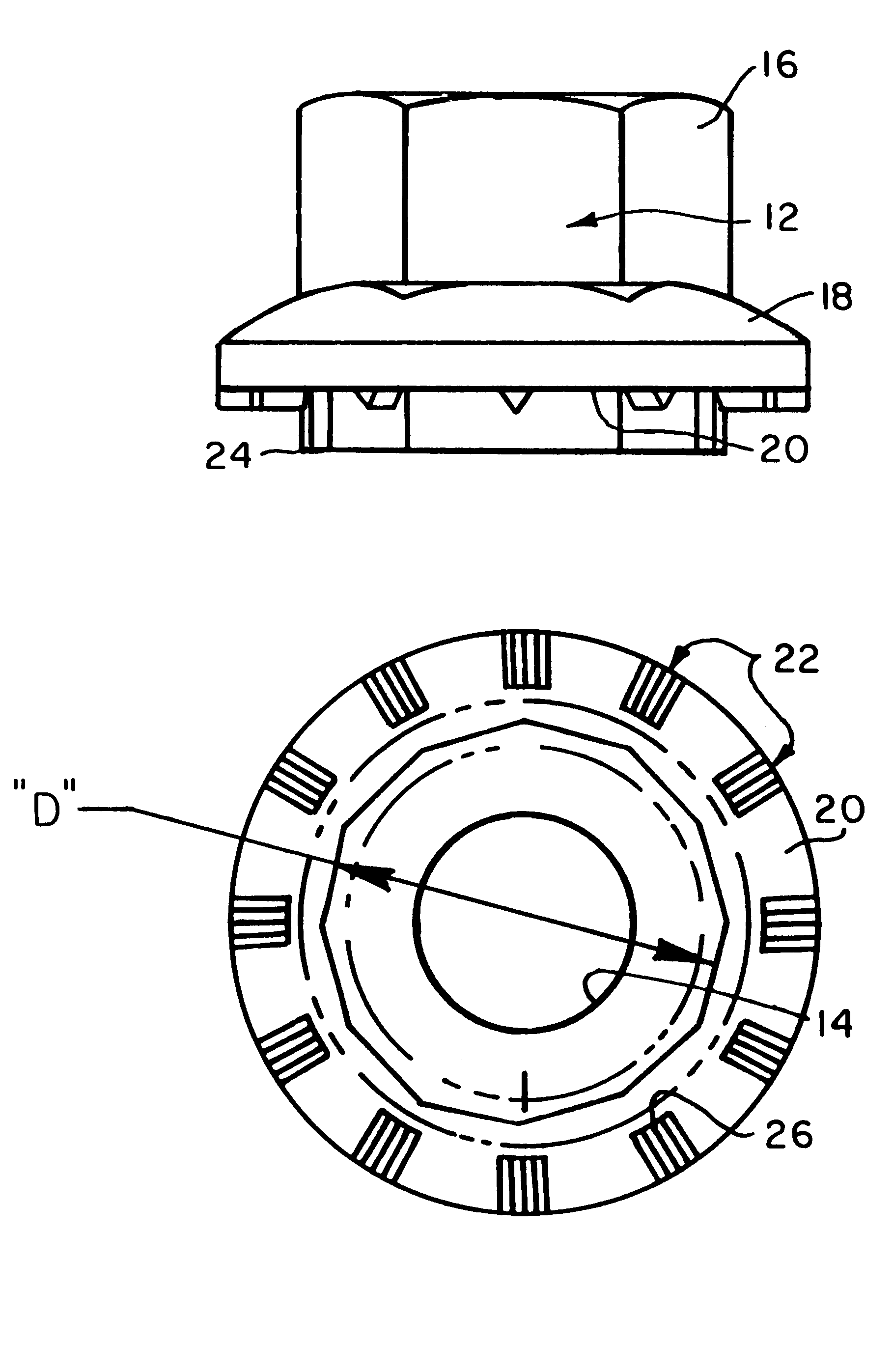
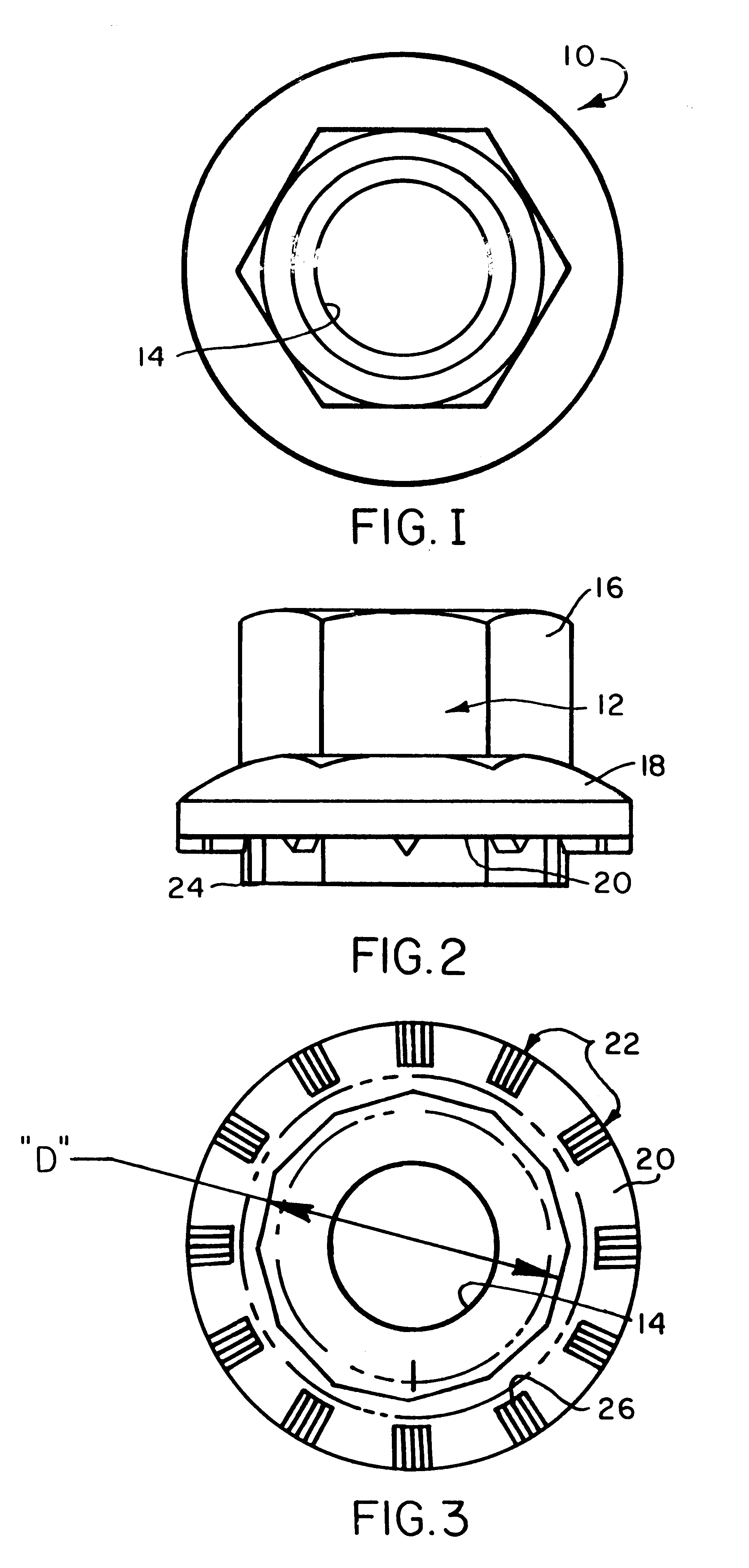
Turning now to the drawing, and particularly FIGS. 1-3, the fastener 10 of the invention is seen to include a one-piece generally cylindrical metal body 12 having a central bore 14 which is threaded where the fastener is contemplated to function as a nut. One end portion 16 is formed into a polygonal shape (e.g., hexagonal) enabling gripping securement by a wrench during tapping, for example. A continuous circular flange 18 extends about the fastener body defining a boundary limit for the end portion 16 and including a surface 20, which faces oppositely from the end portion 16. The surface 20 is formed into a plurality of gripping means 22 arranged at equal angle spacing about the fastener bore axis.

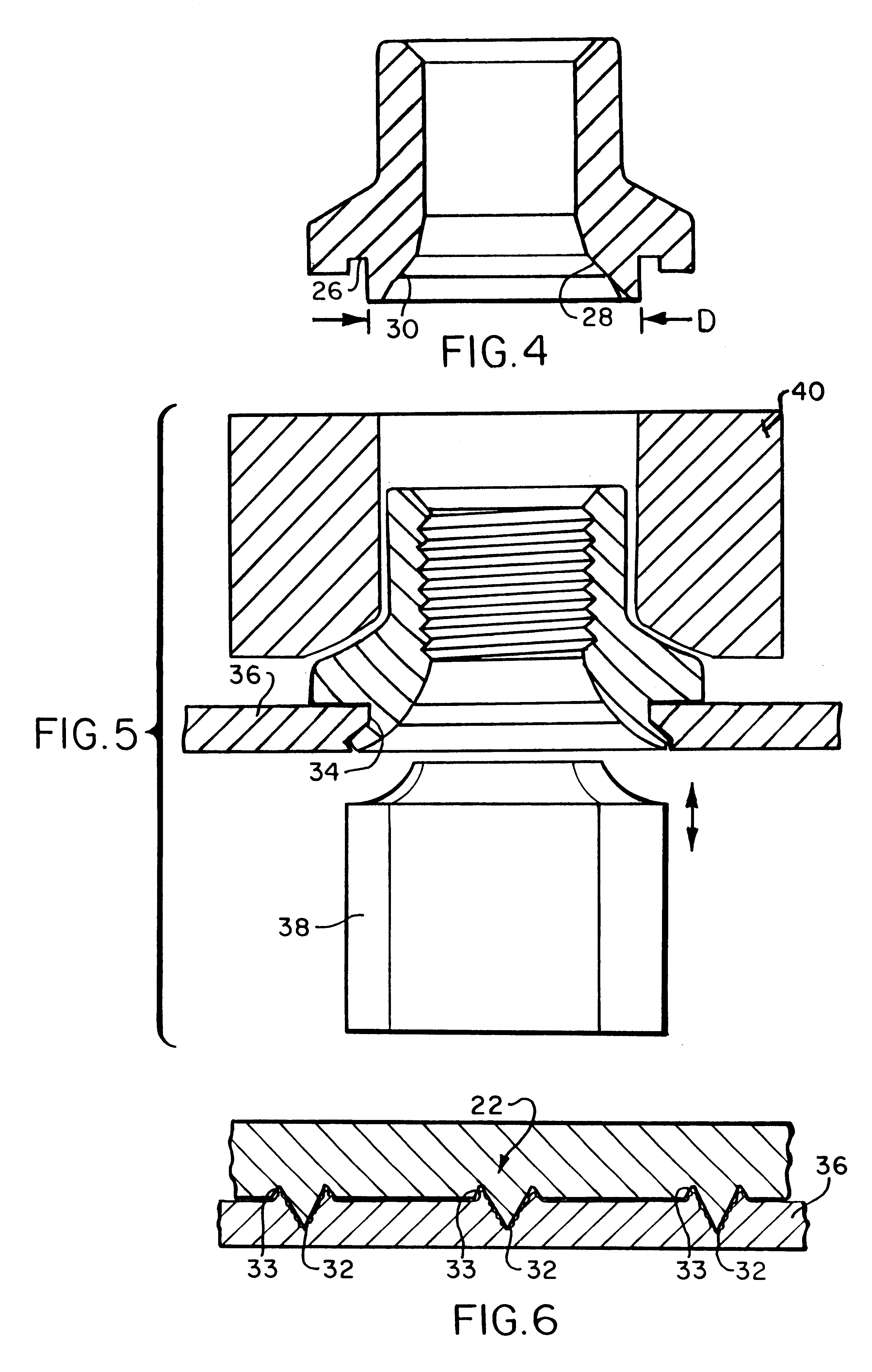
A locking insert 24 with its outer lateral surface formed into a polygon cross-section with a plurality of flats 25 (e.g., 12) extends axially away from the flange and has an external maximum dimension D. A continuous groove 26 in the fastener body 12 separates the outer wall of insert 2...


PUM


Abstract

A fastener (10) for locking receipt in an opening (34) of panel (36) has an upper end portion (16), a flange (18), and a locking insert (24) for receipt in the opening (34) and forcibly distended to prevent removal of the fastener from the opening. A number of gripping means (22) formed in a surface of the flange (18) each include a knifelike edge (32) with a slot (33) at each side thereof. The gripping means bite into the panel providing purchase resisting rotation of the fastener relative to the panel.

Description

1. Background of the InventionThe present invention relates generally to a fastener such as a flange nut, for example, for locking securement within a panel opening. More particularly, the fastener of this invention achieves improved securement of the fastener within the panel opening against all forms of relative movement (e.g., axial, rotation, rocking).2. Description of Related ArtFasteners such as so-called clinch fasteners are known and generally include parts which, on being mounted to a panel opening, deform the panel to grip or clinch the fastener providing desired fixed securement of the fastener.U.S. Pat. No. 3,967,669, CLINCH TYPE FASTENER, by Ronald J. Egner, includes a fastener with a nose portion of cross-section exceeding that of a metal plate opening to receive the fastener, and a locking groove that separates the nose portion from the fastener head. On installation, the nose portion cold works the opening to a larger size which forces plate metal into the locking gr...

Claims


Application Information

Patent Timeline
IPC IPC(8): B23P19/06F16B37/04F16B37/06
CPCB23P19/062F16B37/068
Inventor MITTS, RICHARD K.
Owner ILLINOIS TOOL WORKS INC
Why Eureka
Try Eureka