Bolting configuration for joining ceramic combustor liner to metal mounting attachments

a technology of mounting brackets and combustor lines, which is applied in the direction of machines/engines, mechanical equipment, light and heating equipment, etc., can solve the problems of inability to braze or weld metal blocks, and inconvenient design and achieve the effect of simplifying the fabrication of cmc combustor lines and adequate design li

Active Publication Date: 2009-06-16
GENERAL ELECTRIC CO
View PDF33 Cites 74 Cited by
  • Summary
  • Abstract
  • Description
  • Claims
  • Application Information

AI Technical Summary

Benefits of technology

[0007]In an exemplary embodiment of this invention, a rigid attachment between a CMC combustor liner and metal mounting attachments is provided. Specifically, a unique fastening system provides for positive clamping to allow loadings in the CMC liner to be carried in friction and thus insure adequate design life. The fastening configuration disclosed herein transfers the manufacturing complexity to the bolt itself, thereby simplifying fabrication of the CMC combustor liner.
[0008]More specifically, the CMC liner axial pressure load is carried positively in friction by a clamped fastener configuration that can be treated against susceptibility to wear in the high-vibration gas turbine environment. The clamped joint configuration utilizes a combination of metals to compensate for the low CTE of the CMC liner to maintain clamping forces at elevated operating temperatures enabling this attachment system to carry operating loads in friction.

Problems solved by technology

Thus, the challenge in using CMC materials for combustor liners is developing the interfaces to existing metal hardware in a cost-effective system that meets life and cost requirements.
These designs are not appropriate for CMC liners, however, because it is not feasible to braze or weld metal blocks to the CMC liner.

Method used


Image

  • Bolting configuration for joining ceramic combustor liner to metal mounting attachments
  • Bolting configuration for joining ceramic combustor liner to metal mounting attachments
  • Bolting configuration for joining ceramic combustor liner to metal mounting attachments

Examples


Embodiment Construction

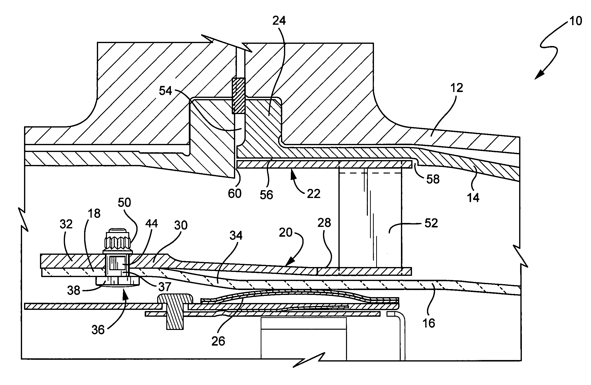
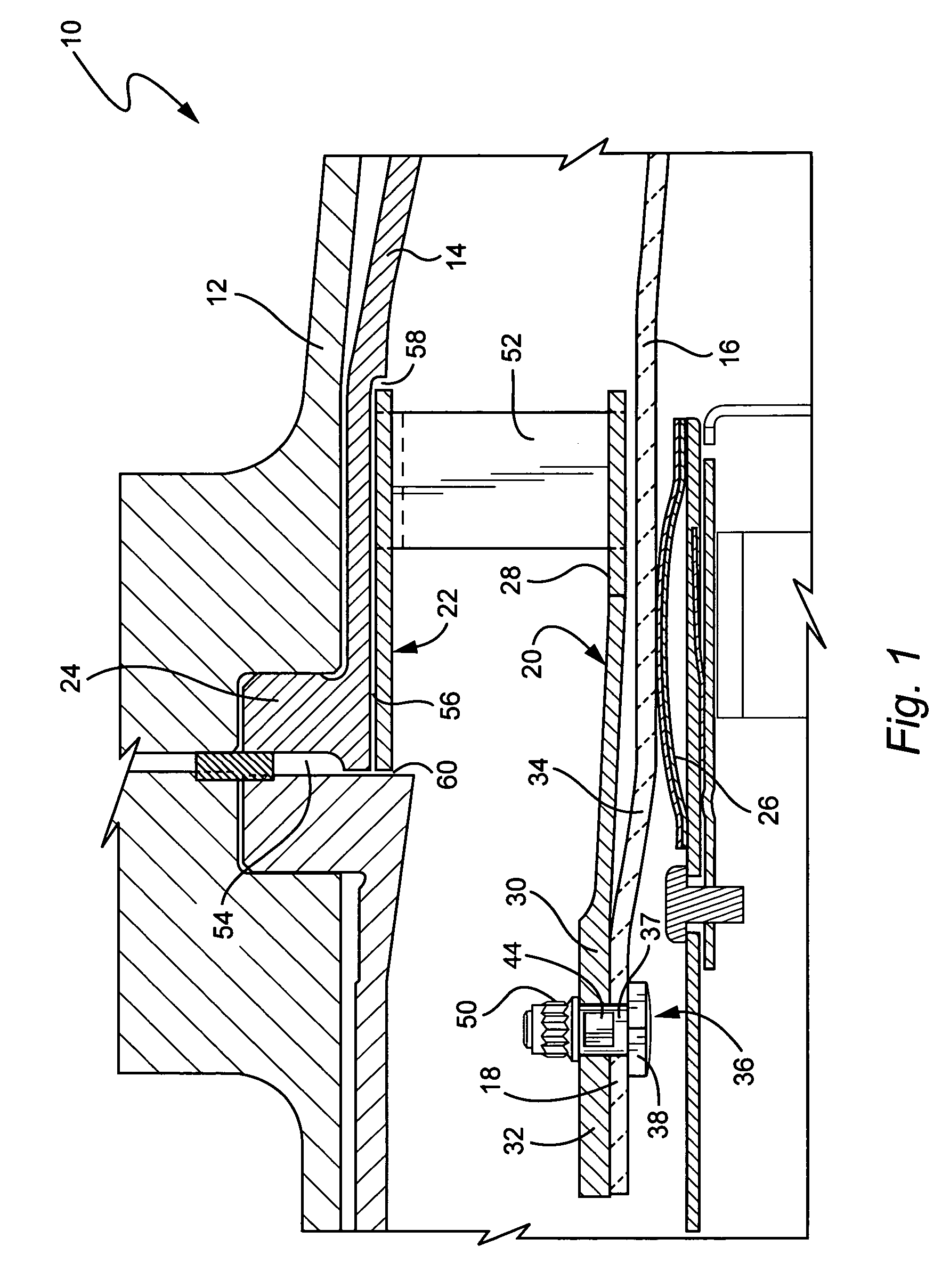
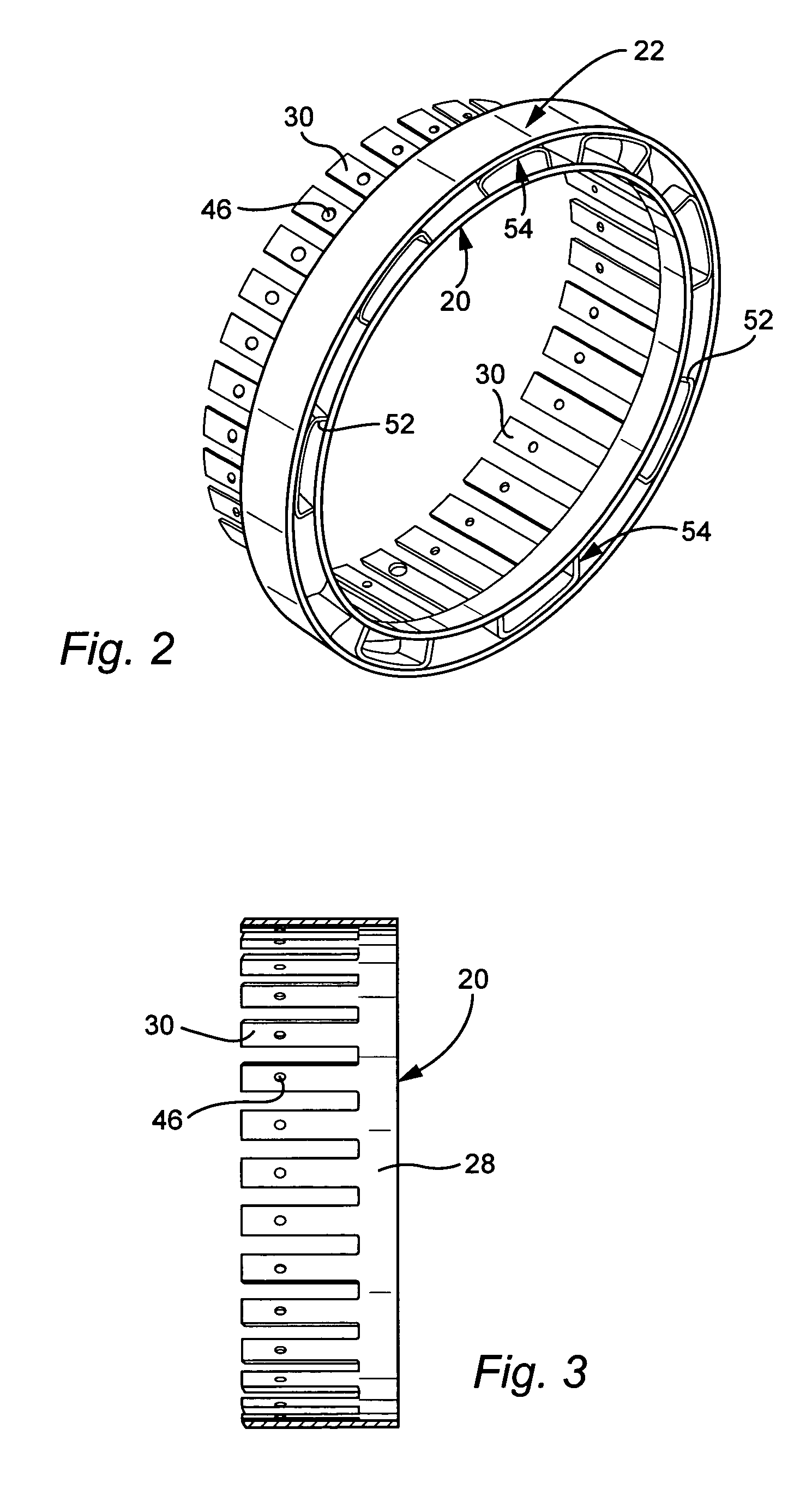
[0024]FIGS. 1 and 2 illustrate a liner configuration for a turbine combustor 10 that includes a combustor casing 12, a radially outer flow sleeve 14 and a radially inner combustor liner 16. The liner 16 and flow sleeve 14 are substantially concentrically arranged within the casing 12, and the invention here relates primarily to the manner in which the forward end 18 of the liner is secured to an inner ring 20 that is in turn attached to a radially outer attachment ring 22.

[0025]In the exemplary embodiment, the liner 16 is made of a non-metallic, low thermal expansion CMC material that can operate at significantly higher temperatures with reduced cooling requirements.

[0026]In order to connect the CMC combustor liner 16 to the metallic attachment hardware at the forward end 18 of the liner, the latter is initially centered from within by conventional hula seals 26 on both the forward and aft ends of the liner. The inner, annular attachment ring 20 is telescoped over the forward end 18...


PUM


Abstract

A gas turbine combustor includes a substantially cylindrical combustor liner located substantially concentrically within a flow sleeve, the combustor liner composed through a ceramic matrix composite material, a forward end of the combustor liner provided with a plurality of circumferentially arranged bolt holes. An inner metal ring is located about an outside surface of the forward end of the combustor liner, the inner metal ring provided with a second plurality of circumferentially spaced bolt holes, with a plurality of bolts extending through the first and second pluralities of bolt holes and secured by self-locking nuts. An outer metal ring is spaced radially outwardly of the inner metal ring, with a plurality of circumferentially spaced struts extending between the inner and outer rings.

Description

BACKGROUND OF THE INVENTION[0001]This invention relates generally to rotating machine technology and, specifically, to an attachment system for securing a ceramics matrix composite combustor liner to metal mounting attachments in a turbine combustor.[0002]Advanced gas turbine engine development has suggested for use in high-temperature applications such as turbine combustor liners, certain non-metallic materials having higher temperature capability than the metal materials currently in use. One specific class of such non-metallic, low thermal expansion materials is ceramic matrix composite (CMC) materials which can operate at significantly higher temperatures than metals, and allow greatly reduced cooling requirements that can be translated into increased engine efficiency and output. With higher temperature capability, CMC materials can also simultaneously allow a reduction in combustor pressure drop by deleting conventional cooling enhancement features such as turbulators.[0003]In...

Claims


Application Information

Patent Timeline
Patent Type & Authority Patents(United States)
IPC IPC(8): F23R3/60
CPCF23R3/007F23R3/60
Inventor BULMAN, DAVID EDWARDDARKINS, JR., TOBY GEORGESCHRODER, MARK STEWARTLIPINSKI, JOHN JOSEPH
Owner GENERAL ELECTRIC CO
Why Eureka
Try Eureka