
Fence hinge

a technology of hinges and hinges, applied in the field of hinges, can solve the problems of gate rails and post members prone to cave, screw holes tearing out of pvc materials, and welded connections that can open and/or crack under normal use,

Active Publication Date: 2011-03-01
EASTERN WHOLESALE FENCE LLC
View PDF22 Cites 21 Cited by
  • Summary
  • Abstract
  • Description
  • Claims
  • Application Information

AI Technical Summary

Benefits of technology

"The invention is a hinge apparatus that allows for easy attachment of a swinging member, such as a door, to a vertical member, such as a fence post. The apparatus includes first and second support members that are attached to the vertical member and the swinging member, respectively, using screws or other fasteners. The first and second support members each have a flange that attaches to the vertical member and the swinging member, creating a secure attachment. The apparatus also includes hinges that connect the first and second support members, allowing for smooth movement of the swinging member. The technical effects of the invention include easy installation, durability, and smooth movement of the swinging member."

Problems solved by technology

One problem that arises with the use of PVC fence gates is caused by welded connections being weak, and thus the welded connections can open and / or crack under normal usage.
Additionally, another problem with PVC gates, for example, arises when the user or installer attempts to attach metallic parts directly to the PVC material.
In many instances, there is a tendency for the screws to tear out of the PVC material.
However, if these support members are bolted too tightly, the gate rail and post members tend to cave in.
In addition, the use of nuts and bolts results in a connection that is aesthetically unappealing.

Method used


Image

  • Fence hinge
  • Fence hinge
  • Fence hinge

Examples


Embodiment Construction

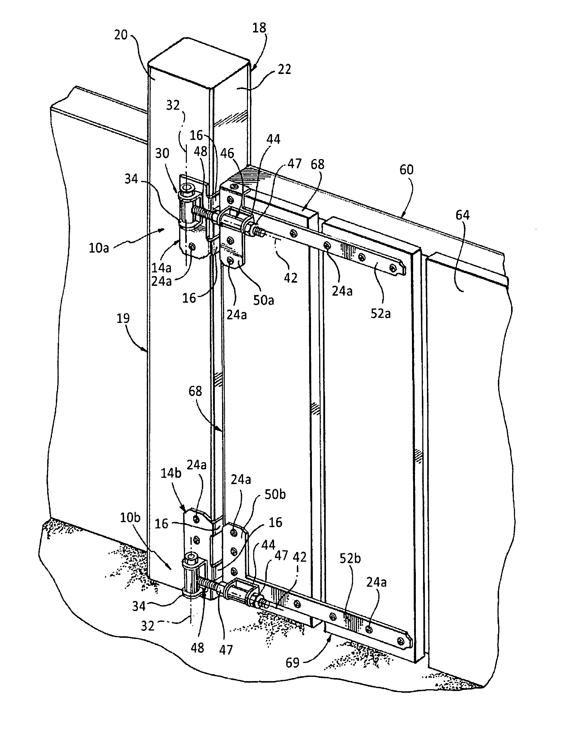
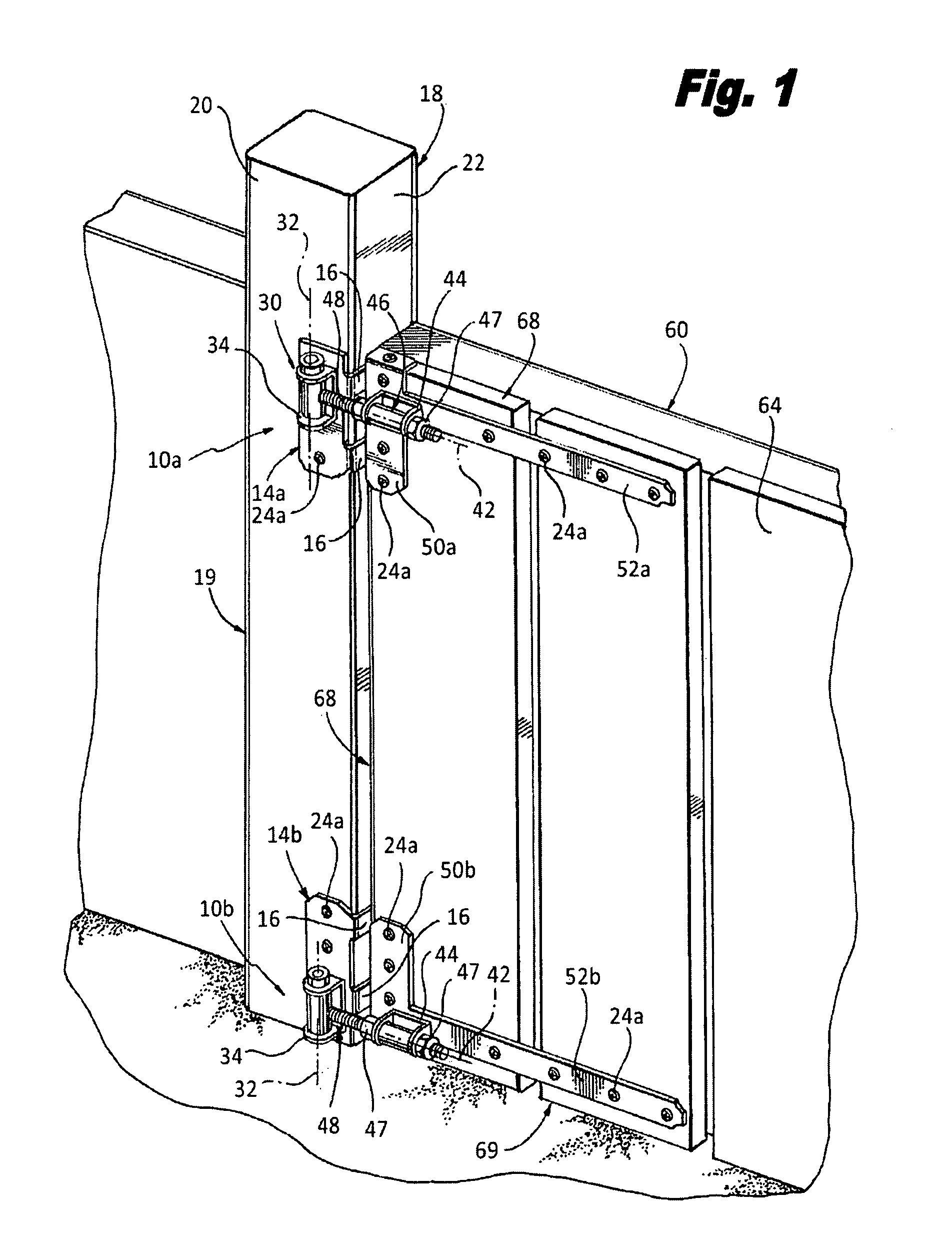
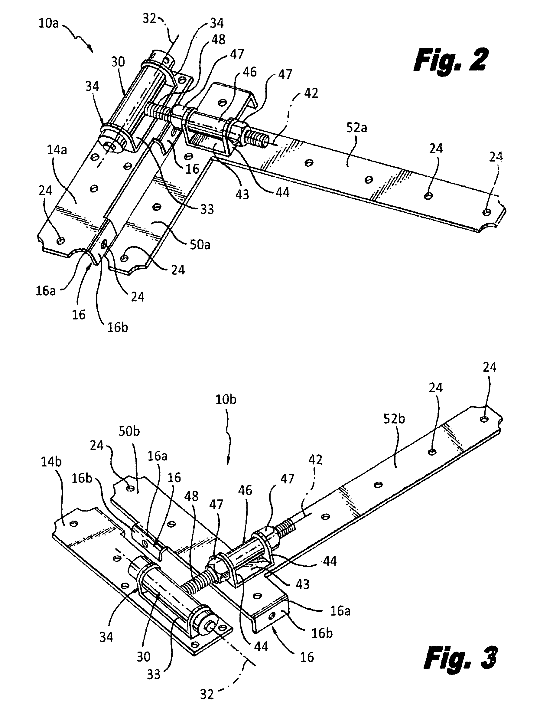
[0023]Referring to FIGS. 1-5, wherein like elements have the same reference numerals, a hinge apparatus according to the invention is shown in the illustrative embodiments as upper and lower hinge apparatuses 10a, 10b. The upper and lower hinge apparatuses 10a, 10b include top and bottom first support members 14a, 14b, respectively, for attachment along a first surface 20 of a vertical member embodied as a fence post 18, shown in FIG. 1. Alternatively, top and bottom first support members 14a, 14b can be attached to a door frame or a first surface 82 of a wall 80, as shown in FIGS. 4 and 5. Both the top and bottom first support members 14a, 14b include two flanges 16 in spaced relation from each other, as best seen in FIG. 2.

[0024]Referring to FIGS. 2 and 3, the flanges 16 extend from the first support members 14a, 14b and are each bent at a ninety degree (90°) angle defining a first portion 16a contiguous with the top and bottom first support members 14a, 14b, and a second portion ...


PUM

PropertyMeasurementUnit
angleaaaaaaaaaa
angleaaaaaaaaaa
distanceaaaaaaaaaa

Abstract

A hinge apparatus includes a first support member for attachment along a first surface of a vertical member such as a fence post. The first support member includes at least one flange angularly extending from the first support member for attachment along a second surface adjacent to the first surface of the vertical member. A hinge coupled to the first support member, and a second support member includes an extended element coupled to the hinge. The second support member attaches to a first surface of a swinging member, such as a fence gate, opposite the first support member. The second support member includes at least one flange angularly extending from the second support member for attachment along a second surface of the swinging member adjacent to the first surface of the swinging member.

Description

FIELD OF THE INVENTION[0001]The present invention relates to hinges, and more specifically, relates to a hinge assembly for a gate or door.BACKGROUND OF THE INVENTION[0002]Polyvinyl chloride (PVC) is commonly used in the manufacture of fencing and fence components. For example, fence gates may be built by first cutting each end of two standard length PVC gate posts and two standard length PVC gate rails. The ends of the fence posts and rails are then welded together to form a rectangular gate structure. One problem that arises with the use of PVC fence gates is caused by welded connections being weak, and thus the welded connections can open and / or crack under normal usage. Additionally, another problem with PVC gates, for example, arises when the user or installer attempts to attach metallic parts directly to the PVC material. In many instances, there is a tendency for the screws to tear out of the PVC material.[0003]In an attempt to strengthen PVC fences, support members are used ...

Claims


Application Information

Patent Timeline
Patent Type & Authority Patents(United States)
IPC IPC(8): E05D7/04
CPCE05D5/06E05D3/10E05D7/0423E05Y2800/676E05Y2900/146Y10T16/53225E06B11/04Y10T16/5595Y10T16/558Y10T16/534E05Y2900/40
Inventor WILLIAMS, JR., PETER E.
Owner EASTERN WHOLESALE FENCE LLC
Learn More