
Cleaning method and cleaning unit of ink ejection section, and image forming apparatus

a technology cleaning method, which is applied in the direction of printing, etc., can solve the problems of poor cleaning efficiency, deterioration of image quality, and deterioration of water repellency of ink ejection section, so as to improve poor ink ejection, efficient removal of ink, and large solubility

Inactive Publication Date: 2011-03-01
KYOCERA DOCUMENT SOLUTIONS INC
View PDF3 Cites 6 Cited by
  • Summary
  • Abstract
  • Description
  • Claims
  • Application Information

AI Technical Summary

Benefits of technology

[0009]An advantage of the present invention is to provide a cleaning method and a cleaning unit of an ink ejection section, and an image forming apparatus which are capable of efficiently removing the ink adhered to the ink ejection section and improving poor ink ejection.
[0010]The present invention is a method of cleaning an ink ejection section in an image forming apparatus that forms an image by ejecting an ink from the ink ejection section. The method includes an ink wiping step for wiping off the ink on the surface of the ink ejection section, a first cleaning step for cleaning the surface of the ink ejection section with a water-soluble organic solvent, a second cleaning step for cleaning with water the surface of the ink ejection section cleaned with the water-soluble organic solvent, and a liquid wiping step for wiping off the liquid on the surface of the ink ejection section cleaned through the second cleaning step.
[0011]Preferably, the water-soluble organic solvent has a solubility parameter (SP value) of 7 to 14. The term “solubility parameter” (unit: (cal / cm3)1 / 2) is a numerical value indicating the polarity of a material. A smaller SP value difference between a solute and a solvent produces a larger solubility.
[0012]According to the present invention, the ink solidified at the ink ejection section can be efficiently removed to enable improvement of poor ink ejection by wiping off the ink on the surface of the ink ejection section before the cleaning step, and further cleaning the surface of the ink ejection section with the water-soluble organic solvent. Additionally, the water repellency of the surface of the ink ejection section can be recovered to reduce image quality deterioration by cleaning and removing with water the water-soluble organic solvent remaining on the surface of the ink ejection section.
[0013]A cleaning unit of the present invention suitable for practicing the above cleaning method is shiftably mounted in an image forming apparatus provided with an ink ejection section having an ink ejection surface capable of ejecting an ink. The cleaning unit includes a first blade member for wiping off an ink contactable with the ink ejection surface, a first porous member impregnated with a water-soluble organic solvent, a second porous member impregnated with water, and a second blade member for wiping off liquid contactable with the ink ejection surface. The first blade member, the first porous member, the second porous member and the second blade member are arranged in the order named along the shift direction of the cleaning unit.
[0014]An image forming apparatus of the invention includes at least an image formation section provided with an ink ejection section having an ink ejection surface capable of ejecting an ink, and further includes the above cleaning unit.

Problems solved by technology

However, if the ink cannot be completely absorbed by the porous elastic body, cleaning efficiency becomes poor, and the water repellency of the ink ejection section is deteriorated by the adhered and dried ink at the ink ejection section.
Thus, the deteriorated water repellency of the ink ejection section leads to deterioration of image quality.
Also in a state in which the resin composition contained in the ink is adhered to the ink ejection section, image quality might also be deteriorated by the difficulty in controlling the ink ejection.
Particularly in an elongated line head, because the amount of ink adhesion is larger than that of a serial head, there is a large possibility that image quality may be deteriorated due to insufficient ink removal.
When the ink is ejected in this state, for example, the solidified resin composition and the ejected ink contact with each other, and the normal ink ejection may be hindered to cause image quality deterioration.

Method used


Image

  • Cleaning method and cleaning unit of ink ejection section, and image forming apparatus
  • Cleaning method and cleaning unit of ink ejection section, and image forming apparatus
  • Cleaning method and cleaning unit of ink ejection section, and image forming apparatus

Examples


first preferred embodiment

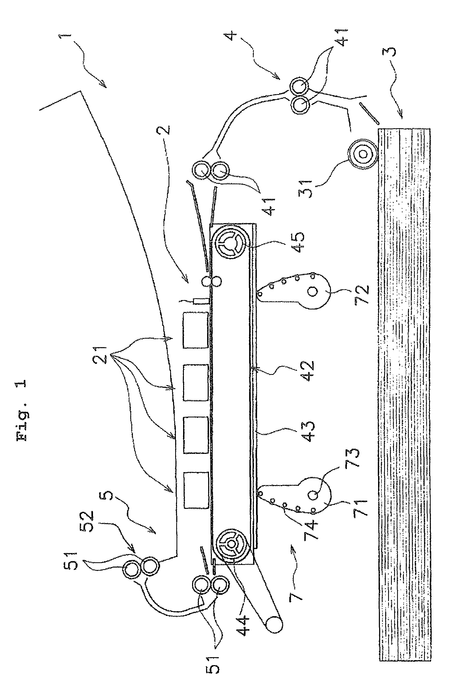
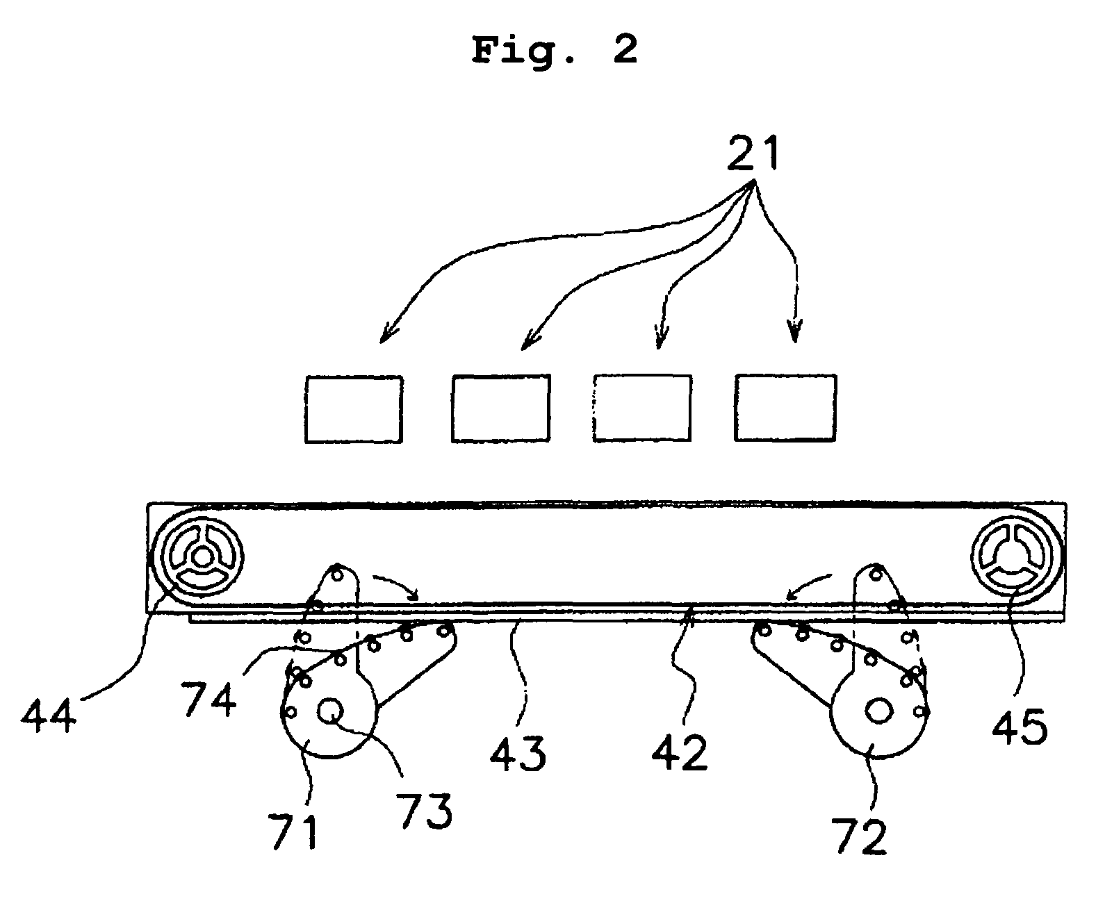
[0022]An inkjet printer 1 as an image forming apparatus according to the invention is shown in FIG. 1. FIG. 1 is a schematic front view schematically showing the configuration of the inkjet printer 1. The inkjet printer 1 is an apparatus which is connected to an external computer or the like (not shown), and capable of forming an image based on image information transmitted from the computer, and which is provided with an image formation section 2, a paper storage section 3, a paper transport section 4, a lift unit 7 and a paper discharge section 5.

[0023]The image formation section 2 forms an image based on image information, and has inkjet heads 21. That is, the four inkjet heads 21 are arranged side by side above a later-described transport belt 42 of the paper transport section 4, and they eject inks onto a paper based on the image information. These inkjet heads 21 store different color inks and have ink ejection sections 211 (refer to FIG. 3) capable of ejecting the inks stored...

second preferred embodiment

[0053]A second preferred embodiment of the invention will be described below and, in some cases, the description of the identical parts to those of the first preferred embodiment will be omitted.

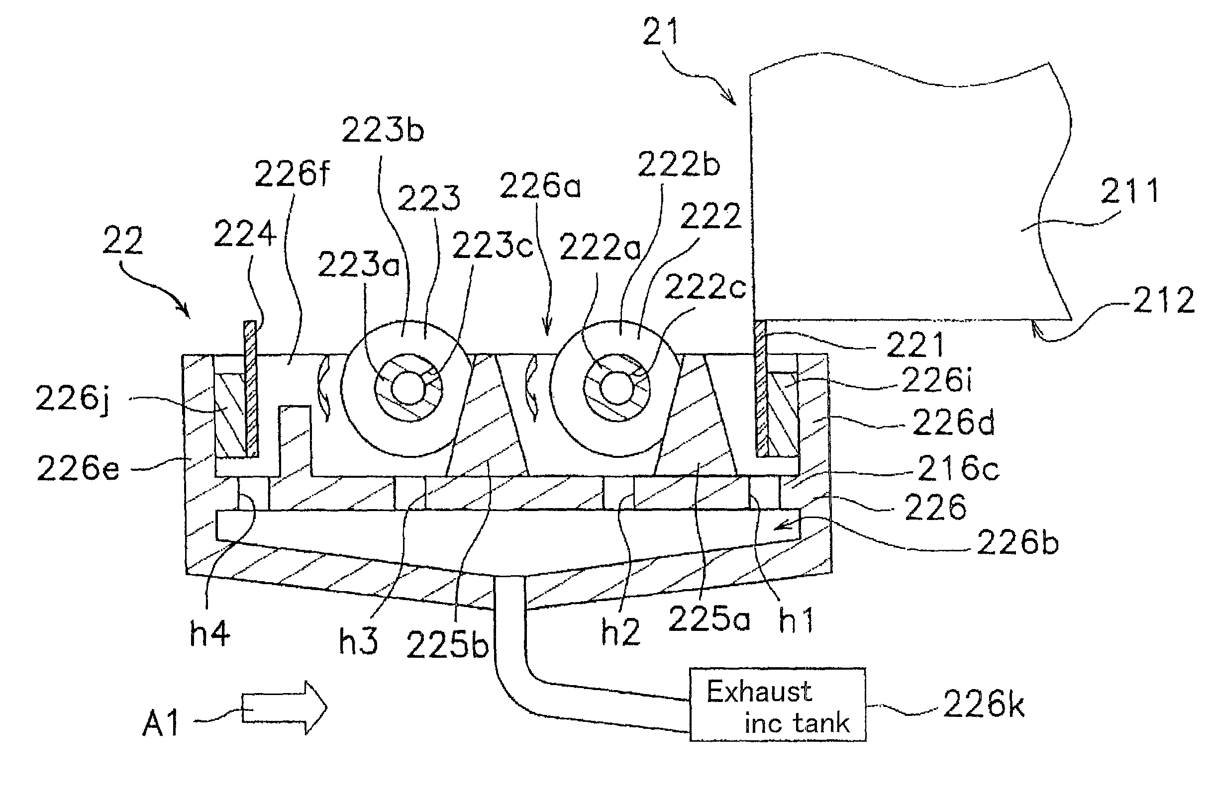
[0054]FIGS. 6 and 7 are overall schematic diagrams of a cleaning unit according to the second preferred embodiment (hereinafter referred to as “second cleaning units 6”). FIG. 6 is a sectional view of each of the second cleaning units 6, and FIG. 7 is a plan view thereof.

[0055]Each of the second cleaning units 6 cleans an ink ejection surface 212, and the width W2 of the second cleaning unit 6, namely the length in a direction perpendicular to the paper surface in FIG. 6 (refer to FIG. 7) is larger than the width in the transverse direction of the ink ejection surface 212. These second cleaning units 6 are provided correspondingly to individual inkjet heads 21, and are connected to an exhaust ink tank 66n. The second cleaning units 6 are shifted in the direction of an arrow A1 in FIG. 5 alon...

example 1

[0073]A pigment dispersion liquid was prepared by mixing 30% by weight of C.I. pigment red 122 as a pigment, 30% by weight of styrene-acrylic resin (“JONCRYL61” manufactured by Johnson Polymer Corporation), 10% by weight of glycerin and 35% by weight of an ion exchanged water, and dispersing this mixture with 0.5 mm zirconia beads by using a ball mill until the mean particle size became 100 nm. The SP value of the used styrene-acrylic resin was 8 to 12. The mean particle size was measured by a dynamic light scattering particle size distribution measuring apparatus (“LB-550” manufactured by HORIBA Ltd.) after the pigment dispersion liquid was diluted five times with the ion exchanged water.

[0074]An ink was prepared by mixing 0.5% by weight of ethylene oxide addition product of acetylene diol as being surfactant (“Olfine E1010” manufactured by Nisshin Chemical Industry Co., Ltd.), 5% by weight of triethylene glycol monobuthyl ether, 5% by weight of 2-pyroridone, 20% by weight of the a...


PUM


Abstract

A method of cleaning an ink ejection section in an image forming apparatus that forms an image by ejecting an ink from the ink ejection section. The method includes the steps of: an ink wiping step for wiping off the ink on the surface of the ink ejection section; a first cleaning step for cleaning the surface of the ink ejection section with a water-soluble organic solvent; a second cleaning step for cleaning with water the surface of the ink ejection section cleaned with the water-soluble organic solvent; and a liquid wiping step for wiping off the liquid on the surface of the ink ejection section cleaned through the second cleaning step.

Description

[0001]Priority is claimed to Japanese Patent Application No. 2008-042635 filed on Feb. 25, 2008, the disclosure of which is incorporated by reference in its entirety.BACKGROUND OF THE INVENTION[0002]1. Field of the Invention[0003]The present invention relates to a cleaning method and a cleaning unit of an ink ejection section in an image forming apparatus such as an inkjet color printer, and to an image forming apparatus.[0004]2. Description of Related Art[0005]In image forming apparatuses, there are apparatuses of the type which forms an image on a paper by ejecting an ink onto a paper as a recording medium, such as inkjet color printers. These image forming apparatuses are provided with an image formation section capable of forming an image, a paper storage section to store a paper whose surface is used for image formation, a paper transport section to transport a paper to the image formation section, and a paper discharge section capable of discharging a paper with an image forme...

Claims


Application Information

Patent Timeline
Patent Type & Authority Patents(United States)
IPC IPC(8): B41J2/165
CPCB41J2/16552B41J2/16585
Inventor FURUKAWA, NORIAKI
Owner KYOCERA DOCUMENT SOLUTIONS INC
Learn More