Protective device and protective measure for a radar system

a radar system and protection device technology, applied in the direction of weapons, instruments, reflecting targets, etc., can solve the problems of occupying precious time during engagement, and the traditional strategy of avoiding emission by turning off the radar emitter is no longer adequate against new arms, so as to achieve important time savings and better targets

Inactive Publication Date: 2011-03-08
OERLIKON CONTRAVES BESCHRAENKTER HAFTUNG
View PDF44 Cites 2 Cited by
  • Summary
  • Abstract
  • Description
  • Claims
  • Application Information

AI Technical Summary

Benefits of technology

[0015]A significant benefit over the traditional protective measures is that the radar device continues to operate even during an attack, thus providing important time savings.
[0017]Furthermore, the cloud comprised of these reflecting decoys, can also be used to manipulate the ARM's own radar because the cloud can present an object larger than the target, thus becoming more attractive to the ARM radar.

Problems solved by technology

Once the attack is over, the radar system is once again activated, which, in turn, takes up precious time during engagement.
Thus, the traditional strategy of avoiding emission by turning off the radar emitter is no longer adequate against new ARMs.

Method used


Image

  • Protective device and protective measure for a radar system
  • Protective device and protective measure for a radar system
  • Protective device and protective measure for a radar system

Examples


Embodiment Construction

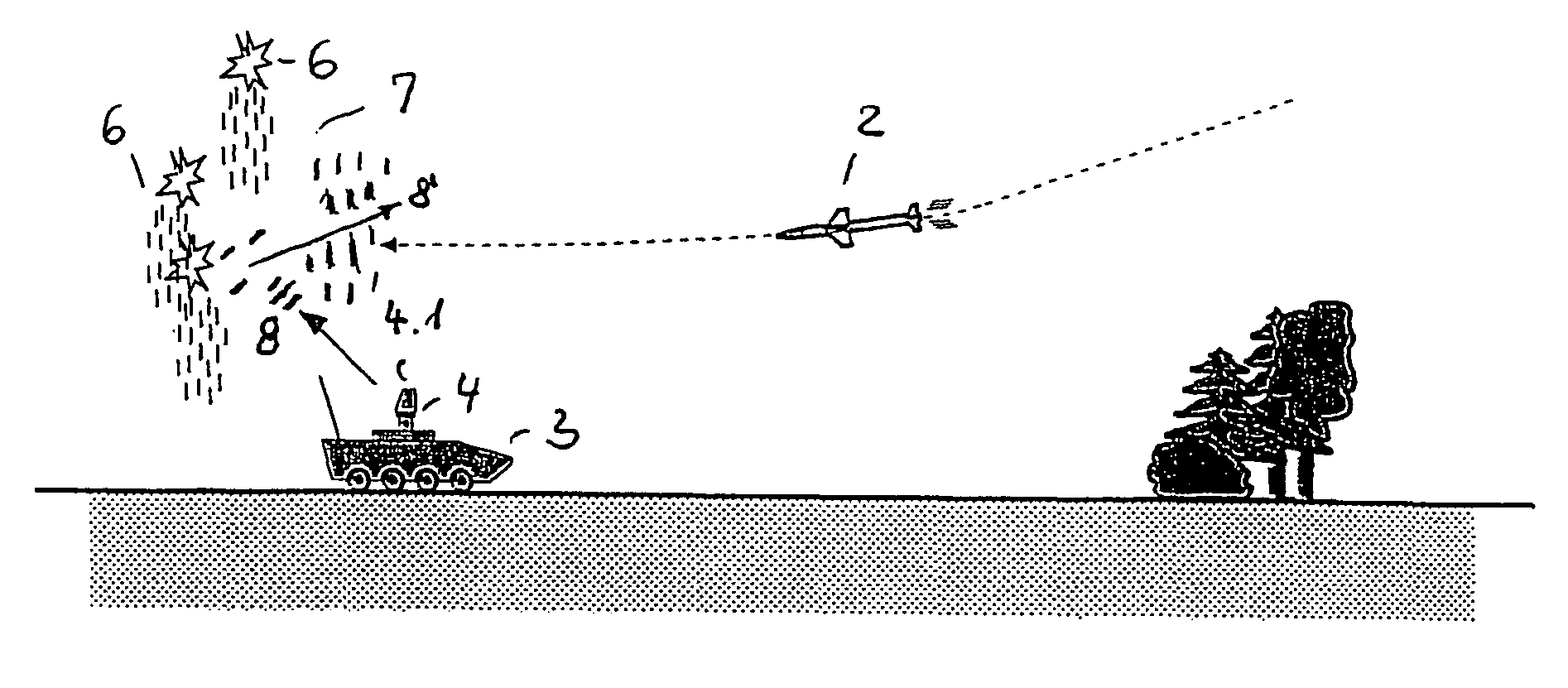
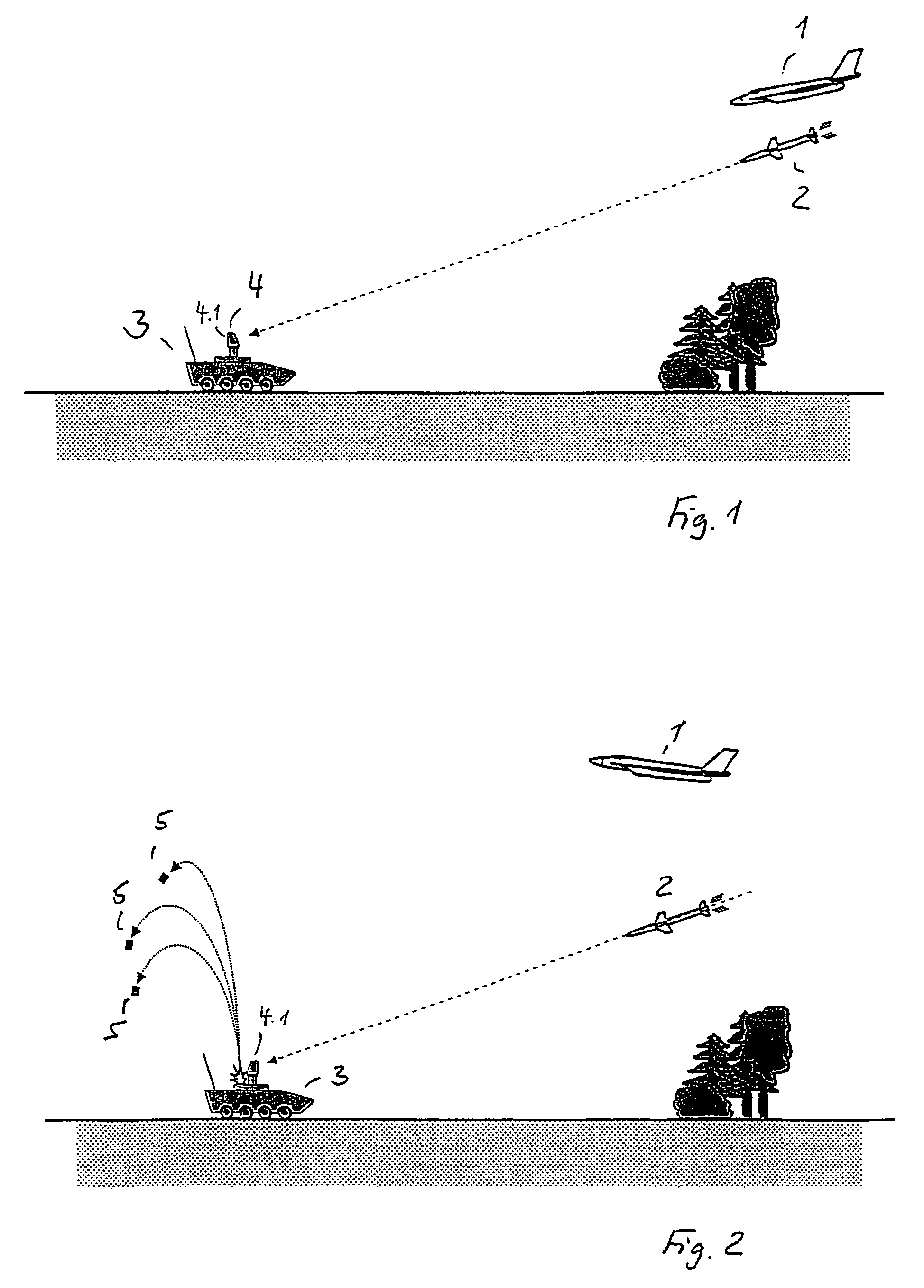
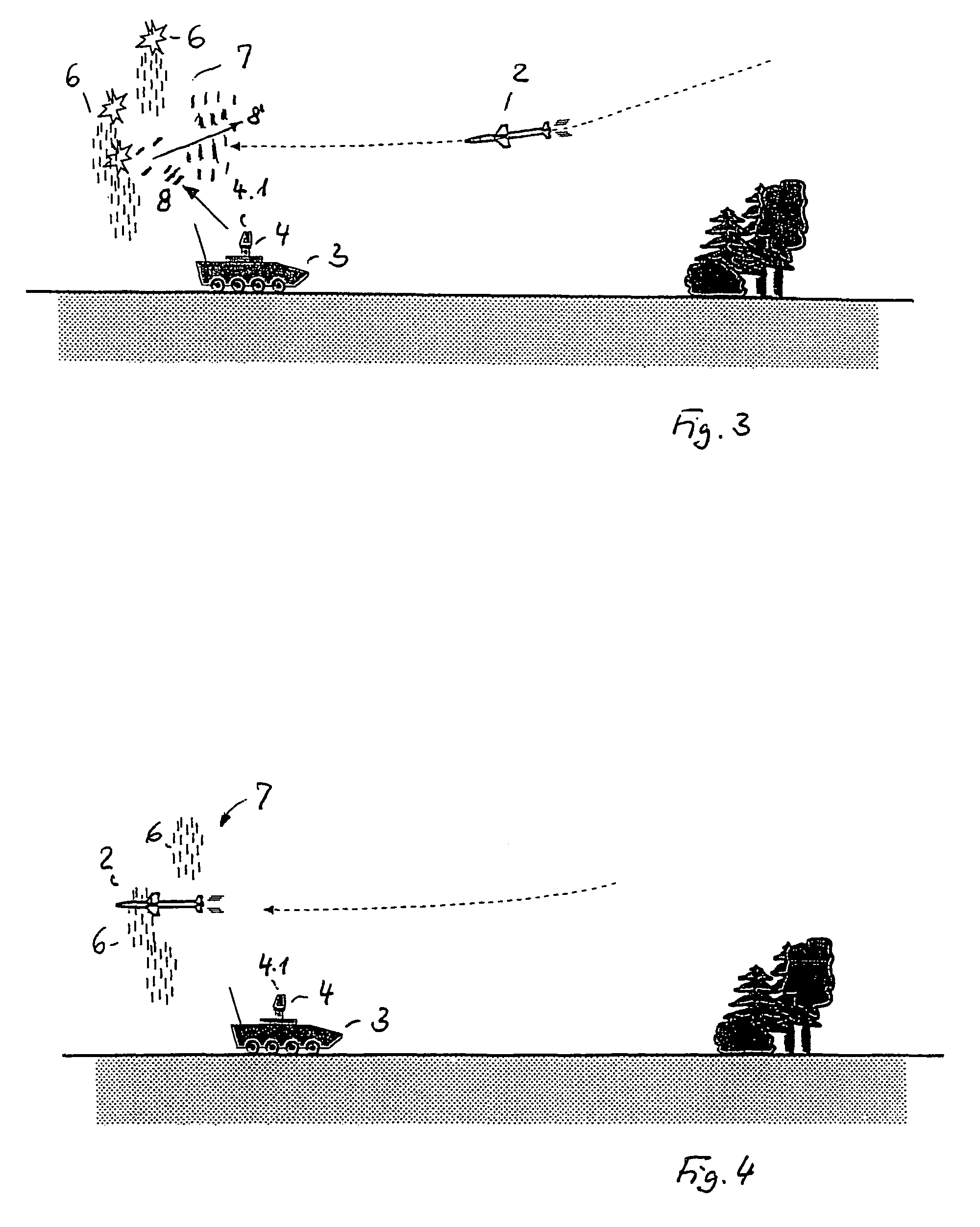
[0023]In FIG. 1, an exemplary scenario is illustrated, whereby from a launcher 1, for example, an aircraft, an ARM 2 is aimed at a vehicle 3 with radar 4, whereby the ARM 2 locks onto the radar signal of radar 4. Radar 4 can be the SKYRANGER Search Radar and Control Centre owned by Oerlikon Contraves AG, for example. In this circumstance, the Search Radar detects the incoming ARM and activates the countermeasure, that is, the protective measure.

[0024]The rotating radar antenna 4.1 is stopped, and oriented in a direction that is opposite to the flight direction of the ARM 2. At roughly the same time, the decoys 5 are thrust upwards, that is, are launched (FIG. 2), which then, radiated by the vehicle's 3 own radar 4, represent an emission source for the ARM 2, to which it locks on, as illustrated in FIG. 3, to fly past the radar 4, and thus past the vehicle 3, at substantially that height (FIG. 4).

[0025]The decoys 5 can be provided in a container (not further illustrated) in vehicle 3...


PUM


Abstract

A protective device and protective measure for a radar system is provided that includes an active countermeasure by using passive emitter and / or decoys. Decoys are thereby utilized that function according to the reflection principle. These decoys are thereby radiated by the vehicle's radar. The radiation reflected by the decoys in the direction of the ARM has the same characteristic as the direct radiation from the radar itself. Thus, the ARM is unable to discriminate between decoys and the actual radar.

Description

[0001]This nonprovisional application claims priority to Provisional Application No. 60 / 899,415, which was filed on Feb. 5, 2007, and to German Patent Application No. DE 102006017107, which was filed in Germany on Apr. 10, 2006, and which are both herein incorporated by reference.BACKGROUND OF THE INVENTION[0002]1. Field of the Invention[0003]The present invention relates to a protective device as well as a protective measure for a radar system against an object, in particular against an anti-radiation-missile (ARM) attack.[0004]2. Description of the Background Art[0005]If a stationary and / or mobile radar system is attacked by an ARM, it has been common practice to turn the radar system off. Once the attack is over, the radar system is once again activated, which, in turn, takes up precious time during engagement.[0006]New ARMs are now prepared for this defense tactic, and are looking for their target by other means. For this purpose, they are now equipped with IR seeker heads, acti...

Claims


Application Information

Patent Timeline
Patent Type & Authority Patents(United States)
IPC IPC(8): H01Q15/14H01Q15/00
CPCF41H11/02F41J2/00F42B12/70
Inventor FRICK, HENRY ROGER
Owner OERLIKON CONTRAVES BESCHRAENKTER HAFTUNG
Why Eureka
Try Eureka