Rotary wing aircraft with a structural arrangement that comprises an electrically conductive connection

a technology of structural arrangement and electrical connection, which is applied in the direction of aircraft static dischargers, connection contact members, etc., can solve the problems of reducing the electrical current flow capacity between respective adjacent fiber reinforced polymer components, and high electrical resistance, so as to improve the electrical connection of the thin metal foils and reduce the electrical current flow capacity. , the effect of high and constant quality

Active Publication Date: 2019-12-17
AIRBUS HELICOPTERS DEUT GMBH
View PDF10 Cites 0 Cited by
  • Summary
  • Abstract
  • Description
  • Claims
  • Application Information

AI Technical Summary

Benefits of technology

[0018]Therefore, fiber reinforced polymer components of structural arrangements, e.g. fiber reinforced polymer components that are used for constructing aircraft structural arrangements, especially in rotary wing aircrafts, or structural arrangements of other vehicles or machines, are according to one aspect at least partly electrically connected to each other by using a thermal gas spray technology. Preferably, each fiber reinforced polymer component therein is provided with a thin metal foil at its selvage and thin metal foils provided at selvages of adjacent fiber reinforced polymer components are electrically connected to each other. Thereby, a small slot between the thin metal foils may be created, which may lead to a reduced electrical current flow capacity between the thin metal foils and, thus, the respective adjacent fiber reinforced polymer components. Consequently, by building up a metal bridging layer respectively bridging layers at the location of the small slot between the thin metal foils by means of the thermal spray or thermal gas spray technology, at least an improved electrical connection of the thin metal foils can be achieved.
[0019]Advantageously, by using the thermal gas spray technology, at least an improved and preferably a high and constant quality electrical connection of thin metal foils provided at adjacent fiber reinforced polymer components can be achieved. Therein, the thermal gas spray technology is preferentially implemented by means of an automated process. Thus, a significant cost reduction and important time savings can be realized, while generally obtaining a smooth outer surface of electrically connected fiber reinforced polymer components.

Problems solved by technology

However, between the fiber reinforced polymer components that are attached to such structural elements, usually an interspace or gap is formed, which leads to an undesired and disadvantageous, comparatively high electrical resistance, which must at least be reduced and, preferably, be avoided.
Thereby, a small slot between the thin metal foils may be created, which may lead to a reduced electrical current flow capacity between the thin metal foils and, thus, the respective adjacent fiber reinforced polymer components.

Method used


Image

  • Rotary wing aircraft with a structural arrangement that comprises an electrically conductive connection
  • Rotary wing aircraft with a structural arrangement that comprises an electrically conductive connection
  • Rotary wing aircraft with a structural arrangement that comprises an electrically conductive connection

Examples


Embodiment Construction

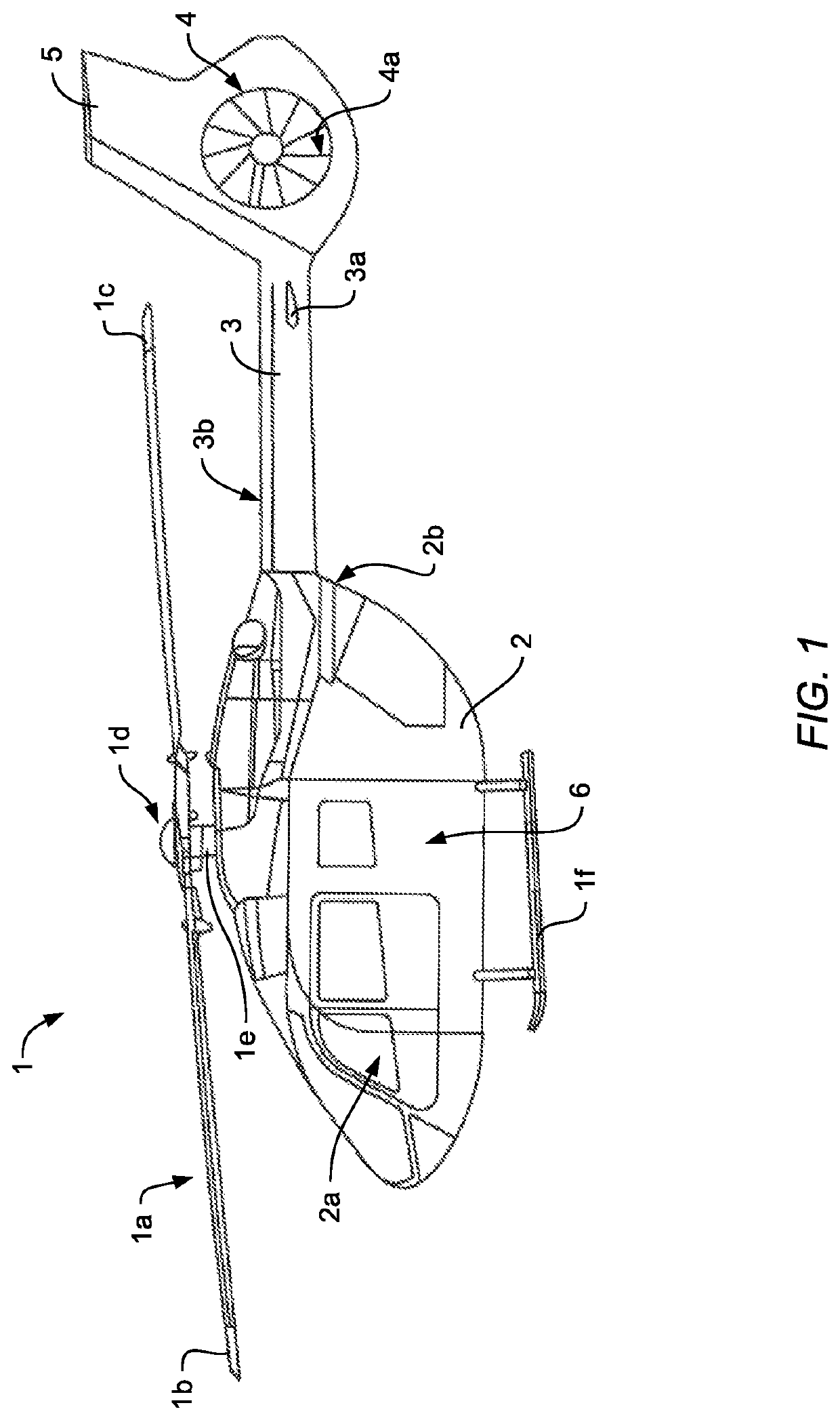
[0043]FIG. 1 shows an aircraft 1 that is exemplarily illustrated as a rotary wing aircraft and, more particularly, as a helicopter. Thus, for purposes of simplicity and clarity, the aircraft 1 is hereinafter referred to as the “helicopter”1.

[0044]Illustratively, the helicopter 1 comprises a fuselage 2 that is connected to a landing gear 1f and defines a cabin 2a and a rear fuselage 2b. The rear fuselage 2b is connected to a tail boom 3.

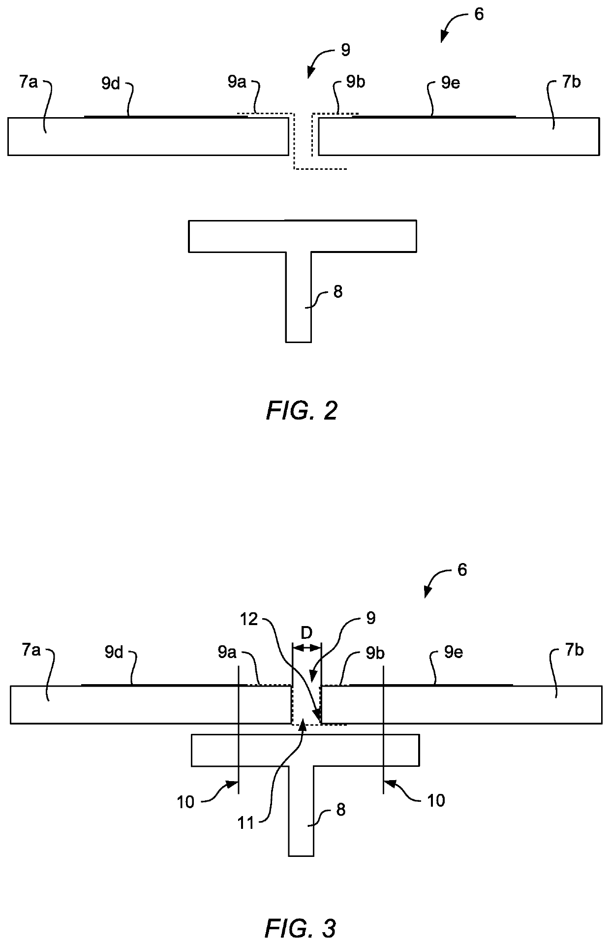
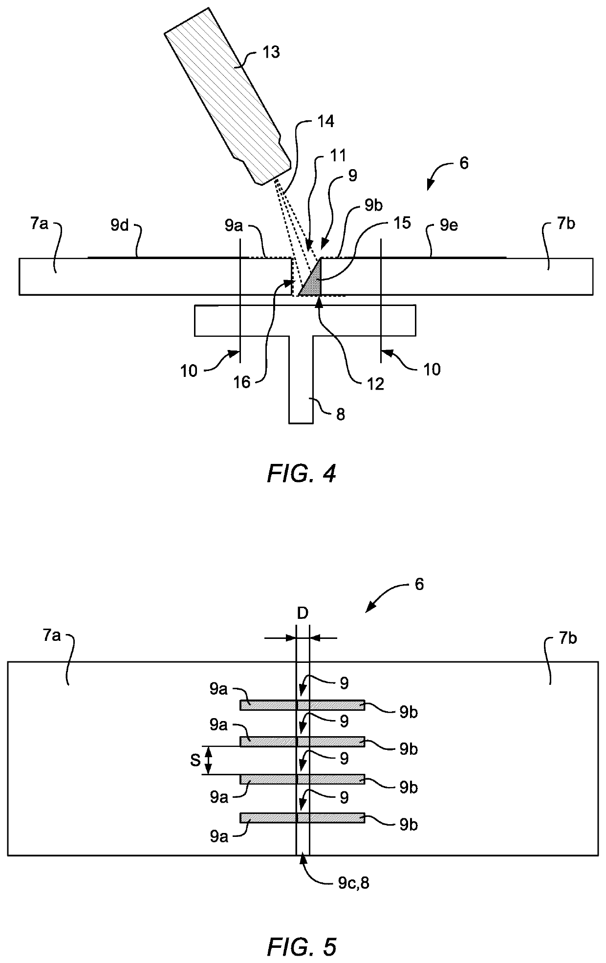
[0045]According to one aspect, the fuselage 2 comprises at least one structural arrangement 6, or embodies the structural arrangement 6, which is preferably implemented using at least two fiber reinforced polymer components (7a, 7b in FIG. 2). The structural arrangement 6 is exemplarily and representatively described in detail below with respect to FIG. 2 to FIG. 8.

[0046]Illustratively, the helicopter 1 further comprises at least one multi-blade main rotor 1a for providing lift and forward or backward thrust during operation. The at least one multi-bl...


PUM

PropertyMeasurementUnit
widthaaaaaaaaaa
widthaaaaaaaaaa
electrical resistanceaaaaaaaaaa

Abstract

A rotary wing aircraft that comprises a structural arrangement with at least one first fiber reinforced polymer component and at least one second fiber reinforced polymer component that are spaced apart from each other by an interspace and that are rigidly attached to an associated structural component, wherein the at least one first fiber reinforced polymer component and the at least one second fiber reinforced polymer component are at least partly interconnected by means of an electrically conductive connection, and wherein the electrically conductive connection comprises at least one sprayed layer of electrically conductive particles, the at least one sprayed layer of electrically conductive particles being provided in the interspace.

Description

CROSS-REFERENCE TO RELATED APPLICATIONS[0001]This application claims priority to European patent application No. EP 16400043.2 filed on Sep. 27, 2016, the disclosure of which is incorporated in its entirety by reference herein.BACKGROUND OF THE INVENTION(1) Field of the Invention[0002]The invention is related to a structural arrangement with at least one first fiber reinforced polymer component and at least one second fiber reinforced polymer component that are spaced apart from each other by an interspace and that are rigidly attached to an associated structural component, wherein the at least one first fiber reinforced polymer component and the at least one second fiber reinforced polymer component are at least partly interconnected by means of an electrically conductive connection. The invention is further related to a method of manufacturing such a structural arrangement, as well as to a rotary wing aircraft that comprises such a structural arrangement.(2) Description of Related...

Claims


Application Information

Patent Timeline
Patent Type & Authority Patents(United States)
IPC IPC(8): B64D45/02B05D5/12B64C1/12B05D7/02B05D1/02H01R4/64B32B5/02H01L41/317
CPCB05D7/02B05D5/12H01R4/64B05D1/025B64C1/12B64D45/02B05D2201/02B32B5/022H01L41/317B29C66/721C23C24/04B29L2031/3088B29C66/1122B29L2031/3082B29C66/21B29C66/43B29K2995/0005B29C65/562B29C66/43441B29C66/112B29C66/52441B29C66/7212B29C66/131B29C66/54B29C66/543B29K2307/04B29K2309/08B29K2277/10H10N30/077
Inventor RACK, ANDREASROSPLESCH, DAVIDJONKE, DIETRICH
Owner AIRBUS HELICOPTERS DEUT GMBH
Why Eureka
Try Eureka