Valve bridge with integrated lost motion system

a technology of motion system and valve bridge, which is applied in the direction of valve drives, machines/engines, non-mechanical valves, etc., can solve the problems of excess exhaust gas flowing back into the cylinder and into the intake manifold, braking and egr performance problems, and difficulty in adjusting the timing and/or amount of engine valve li

Active Publication Date: 2011-03-15
JACOBS VEHICLE SYST
View PDF25 Cites 55 Cited by
  • Summary
  • Abstract
  • Description
  • Claims
  • Application Information

AI Technical Summary

Problems solved by technology

The use of fixed profile cams, however, can make it difficult to adjust the timings and / or amounts of engine valve lift to optimize them for various engine operating conditions.
This added valve lift may create an increased overlap between the main exhaust event and the main intake event, and cause excess exhaust gases to flow back into the cylinder and into the intake manifold.
This result may lead to braking and EGR performance issues, such as higher injector tip temperature and lower engine retarding power.
In addition, the added valve lift may cause reliability issues, including increased potential of valve-to-piston contact.
Additional systems that may be added to existing engines are often cost-prohibitive and may have additional space requirements due to their bulky size.
Pre-existing engine brake systems may avoid high cost or additional packaging, but the size of these systems and the number of additional components may often result in lower reliability and difficulties with size.
It is thus often desirable to provide an integral engine braking system that may be low cost, provide high performance and reliability, and yet not provide space or packaging challenges.

Method used


Image

  • Valve bridge with integrated lost motion system
  • Valve bridge with integrated lost motion system
  • Valve bridge with integrated lost motion system

Examples


first embodiment

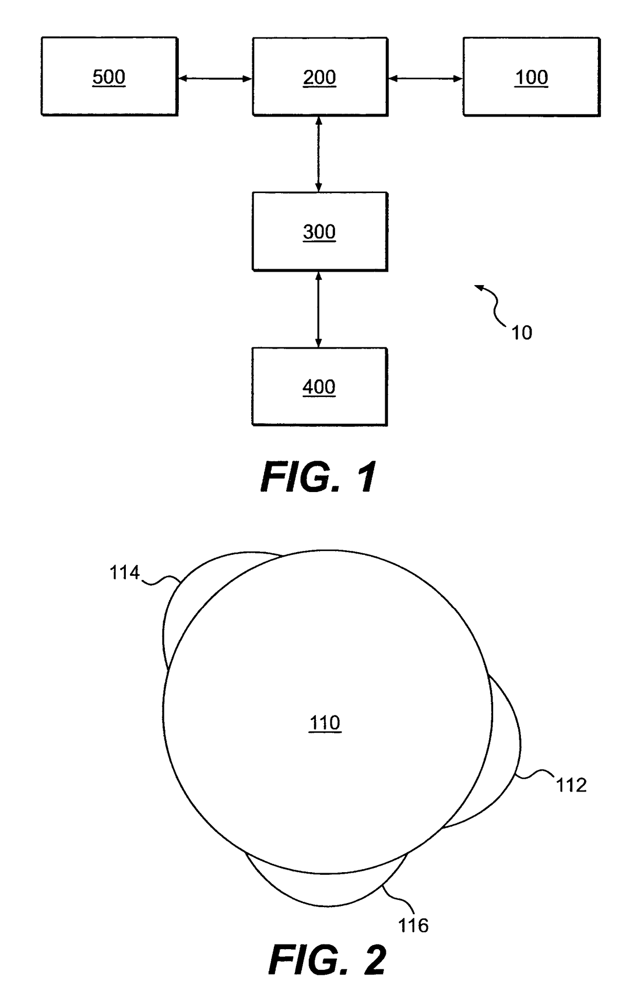
[0038]the present invention is shown schematically in FIG. 1 as valve actuation system 10. The valve actuation system 10 includes means for imparting motion 100 operatively connected to a rocker arm 200. The rocker arm 200 is operatively connected to a lost motion system 300, which in turn, is operatively connected to one or more engine valves 400. The motion imparting means 100 is adapted to selectively apply motion to the rocker arm 200. The lost motion system 300 may be selectively controlled such that all or a portion of the motion from the motion imparting means 100 is (1) transferred or (2) not transferred through the rocker arm 200 to the engine valves 400. The lost motion system 300 may also be adapted to modify the amount and timing of the motion transferred to the engine valves 400. The engine valves 400 may comprise one or more exhaust valves, intake valves, or auxiliary valves.

[0039]When operating in the motion transfer mode, the lost motion system 300 may actuate the en...

second embodiment

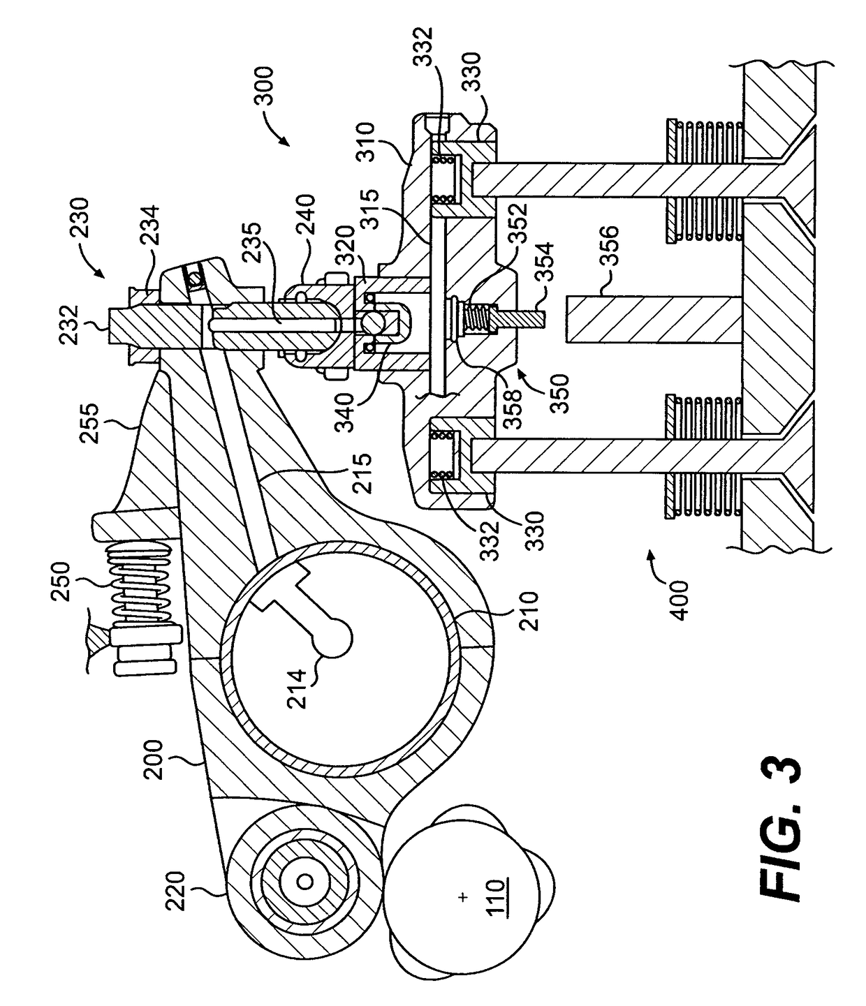
[0042]the present invention is shown in FIG. 3. The rocker arm 200 may be pivotally mounted on a rocker shaft 210 such that the rocker arm 200 is adapted to rotate about the rocker shaft 210. A motion follower 220 may be disposed at one end of the rocker arm 200 and may act as the contact point between the rocker arm 200 and the cam 110 to facilitate low friction interaction between the elements. In one embodiment of the present invention, the motion follower 220 may comprise a roller follower 220, as shown in FIG. 3. Other embodiments of a motion follower adapted to contact the cam 110 are considered to be well within the scope and spirit of the present invention.

[0043]Hydraulic fluid may be supplied to the rocker arm 200 from a hydraulic fluid supply (not shown). The hydraulic fluid may flow through a passage 214 formed in the rocker shaft 210 to a hydraulic passage 215 formed within the rocker arm 200. The arrangement of hydraulic passages in the rocker shaft 210 and the rocker a...


PUM


Abstract

A system and method of actuating one or more engine valves is disclosed. In one embodiment, the system comprises: a valve train element; a rocker arm pivotally mounted on a shaft and adapted to rotate between a first position and a second position, the rocker arm selectively receiving motion from the valve train element; a valve bridge disposed above the one or more engine valves; and a lost motion system disposed in the valve bridge.

Description

CROSS-REFERENCE TO RELATED APPLICATION[0001]This application relates to and claims priority on U.S. Provisional Application No. 60 / 552,745, filed Mar. 15, 2004 and entitled “Valve Bridge With Integrated Lost Motion System,” a copy of which is incorporated herein by reference in its entirety.FIELD OF THE INVENTION[0002]The present invention relates generally to systems and methods for actuating one or more engine valves in an internal combustion engine. In particular, the invention relates to systems and methods for valve actuation including a lost motion system. Embodiments of the present invention may be used during positive power, engine braking, and / or exhaust gas recirculation operation of an internal combustion engine.BACKGROUND OF THE INVENTION[0003]Valve actuation in an internal combustion engine is required in order for the engine to produce positive power, and may also be used to produce auxiliary valve events, such as engine braking, and exhaust gas recirculation (EGR). Du...

Claims


Application Information

Patent Timeline
Patent Type & Authority Patents(United States)
IPC IPC(8): F01L1/26F01L1/08F01L1/18F01L1/24F01L1/30F01L1/34F01L13/06F02D9/06F02D13/04F02M25/07
CPCF01L1/181F01L13/06F02D13/04F01L13/065F02M25/0752F02D9/06F01L1/08F01L1/26F01L1/2416F01L1/267Y02T10/142F02B2275/32F01L2760/004Y10T74/2107F01L2105/00F01L2800/10Y02T10/121F02M26/01F01L2305/00Y02T10/12F01L1/18F01L13/00
Inventor RUGGIERO, BRIANFUCHS, NEILYANG, ZHOUJANAK, ROBB
Owner JACOBS VEHICLE SYST
Why Eureka
Try Eureka