Battery cooling air intake structure

a technology of cooling air and battery, which is applied in the direction of battery/fuel cell control arrangement, cell components, electric devices, etc., can solve the problems of degrading ease of use of seat belts and inability to supply cooling air to batteries, and achieve the effect of preventing interferen

Active Publication Date: 2011-03-15
HONDA MOTOR CO LTD
View PDF15 Cites 68 Cited by
  • Summary
  • Abstract
  • Description
  • Claims
  • Application Information

AI Technical Summary

Benefits of technology

[0016]In accordance with the first aspect of the present invention, when a battery is cooled using, as cooling air, air within the vehicle compartment taken in via the intake port provided in the interior member of the vehicle body side part continuous with the side part of the seat back of the seat for a passenger to sit on, since the seat belt is disposed so that at least part thereof in a non-used state overlaps the intake port and a predetermined gap is formed between a rear face of the seat belt and the intake port, it is possible to prevent interference of the intake of cooling air due to the intake port being blocked by the seat belt while guaranteeing ease of use of the seat belt by disposing it as far toward the outside in the vehicle width direction as possible so that it does not overlap the seat back.
[0017]Furthermore, in accordance with the second aspect of the present invention, since the width of the intake port in the vehicle width direction is larger than the width of the seat belt in the vehicle width direction, it is possible to reliably prevent the intake port from being completely blocked by the seat belt.
[0018]Moreover, in accordance with the third aspect of the present invention, since the front face of the interior member, in which the intake port is provided, is offset further to the rear of the vehicle body than the front face of the seat back, not only is it possible to guarantee a gap between the seat belt and the intake port, but it is also possible to prevent the intake port from being blocked by the body of a passenger sitting on the seat.
[0019]Furthermore, in accordance with the fourth aspect of the present invention, since the gap-forming member, which abuts against the rear face of the seat belt, is projectingly provided on the front face of the interior member, in which the intake port is provided, it is possible to guarantee a gap between the seat belt and the intake port by lifting the seat belt in a non-used state from the intake port toward the front of the vehicle body, and it is possible to yet more reliably prevent the intake port from being completely blocked by the seat belt.
[0020]Moreover, in accordance with the fifth aspect of the present invention, since the extremity portion via which the gap-forming member abuts against the rear face of the seat belt is positioned further to the front of the vehicle body than the front face of the seat back, it is possible to guarantee a large distance between the seat belt and the intake port, thus still more reliably preventing the intake port from being completely blocked by the seat belt.
[0021]Furthermore, in accordance with the sixth aspect of the present invention, since the intake port is inclined so as to be positioned further to the front of the vehicle body the further downward it is and is inclined so as to be positioned further to the rear of the vehicle body the further inward it is in the vehicle width direction, it is possible to guarantee a maximum area for the intake port within a confined space.

Problems solved by technology

In the above-mentioned conventional arrangement, since a front face of the seat back is flush with the front face of the seat side garnish in which the intake port is provided, when a seat belt disposed along the front face of the seat back is in a non-used state, the intake port is blocked by the seat belt and there is a possibility that cooling air will not be able to be supplied to the battery.
If in order to prevent this the seat belt in a non-used state is disposed further inside in the vehicle width direction than the intake port, there is a possibility that the ease of use of the seat belt will be degraded.

Method used


Image

  • Battery cooling air intake structure
  • Battery cooling air intake structure
  • Battery cooling air intake structure

Examples


first embodiment

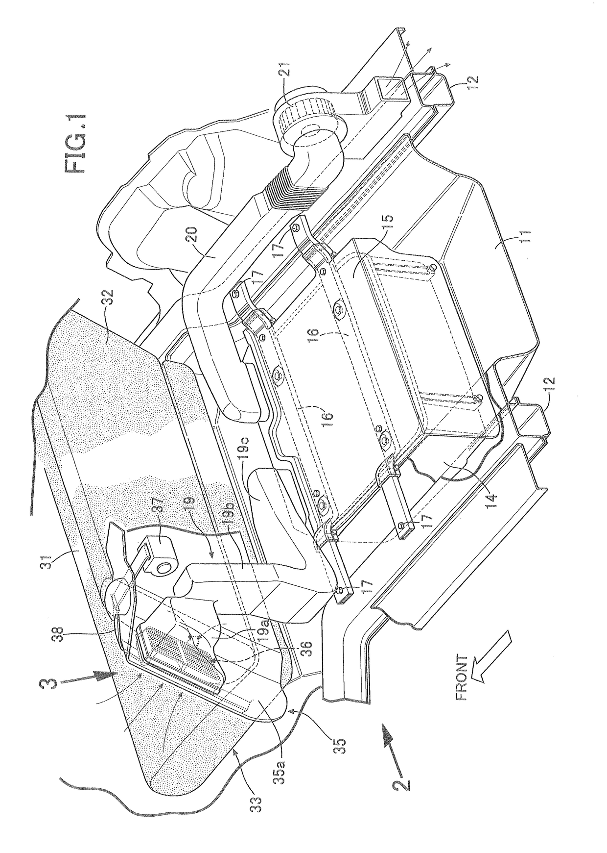
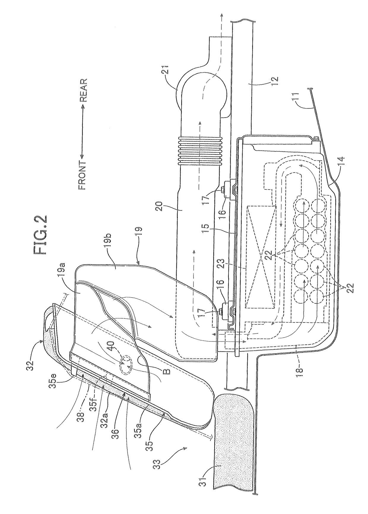
[0049]As shown in FIG. 1 and FIG. 2, a power supply system for operating a motor / generator of a hybrid vehicle is housed by utilizing a tire pan 11 that houses a spare tire beneath a trunk compartment of a vehicle body rear part. The tire pan 11, which has a downwardly recessed container shape, has its left and right side edges connected to left and right rear side frames 12 and 12. The power supply system includes a waterproof case 14 having a container shape with an open upper face, and a flat plate-shaped lid member 15 closing the upper face opening, and opposite end parts, in the vehicle width direction, of a pair of front and rear hanger frames 16 and 16 extending in the vehicle width direction while being held between the waterproof case 14 and the lid member 15 are fixed to upper faces of the left and right rear side frames 12 and 12 by bolts 17. The power supply system is therefore hangingly supported by the left and right rear side frames 12 and 12 via the pair of front and...


PUM

PropertyMeasurementUnit
widthaaaaaaaaaa
distanceaaaaaaaaaa
areaaaaaaaaaaa

Abstract

In a battery cooling air intake structure, in which a trunk side lining (35) of a vehicle body side part is disposed so as to be continuous with a side part of a seat back (32) of a seat for a passenger to sit on, and a battery is cooled using, as cooling air, air within a vehicle compartment taken in via an intake port (36) provided in a front face (35a) of the trunk side lining (35), since a seat belt (38) is disposed so that at least part thereof in a non-used state overlaps the intake port (36) when viewed in the vehicle body fore-and-aft direction and a predetermined gap (b) is formed between the intake port (36a) and at least part of the seat belt (38) when viewed in the vehicle width direction, it is possible to prevent interference with the intake of cooling air due to the intake port (36) being blocked by the seat belt (38), while disposing the seat belt (38) as far toward the outside in the vehicle width direction as possible so that it does not overlap the seat back (32).

Description

CROSS-REFERENCE TO RELATED APPLICATION[0001]This application is a National Stage entry of International Application No. PCT / JP2008 / 072653, filed Dec. 12, 2008, which claims priority to Japanese Patent Application No. 2007-332590, filed Dec. 25, 2007. The disclosure of the prior application is hereby incorporated in its entirety by reference.TECHNICAL FIELD[0002]The present invention relates to a battery cooling air intake structure in which an intake port for taking from within a vehicle compartment, as cooling air, air for cooling a battery is provided in an interior member, in a vehicle body side part, continuous with a side part of a seat back of a seat for a passenger to sit on.BACKGROUND ART[0003]An arrangement in which a battery for an electric automobile or a hybrid vehicle is mounted in a luggage space of a vehicle body rear part, and cooling air for cooling this battery is taken in via an intake port provided in a front face of a seat side garnish continuous with a side par...

Claims


Application Information

Patent Timeline
Patent Type & Authority Patents(United States)
IPC IPC(8): B60K11/00B60K1/04B60K11/06B60R13/02B60R22/24H01M10/60H01M10/613H01M10/625H01M10/651H01M10/6565H01M50/249
CPCB60K1/04B60L3/0046B60L11/1874B60L11/1877B60L11/1879B60R13/02H01M2/1083H01M10/5004H01M10/5016H01M10/5057H01M10/5067H01M10/5073Y02T10/705B60R13/0237B60R2011/0015B60R2013/0287B60R2022/1818H01M10/503Y02T10/7005B60K2001/005H01M10/6556H01M10/6566H01M10/6563H01M10/625H01M10/613H01M10/643B60L58/26B60L50/66B60L50/64H01M50/249Y02T10/70
Inventor KUBOTA, SHINYAKOSAKA, HIROSHINAKAMURA, YOSHINORIKIKUCHI, HIROBUMI
Owner HONDA MOTOR CO LTD
Why Eureka
Try Eureka