Draper header with multiple sided cut crop barrier interface between the cutter bar and draper canvas

Active Publication Date: 2011-03-22
BLUE LEAF I P
View PDF15 Cites 41 Cited by
  • Summary
  • Abstract
  • Description
  • Claims
  • Application Information

AI Technical Summary

Benefits of technology

[0014]As an advantage of the invention, the angularly related closely spaced, face-to-face relationships form a multiple sided interface between the cutter bar and the draper canvas, which acts as a barrier to passage of cut crop and material carried thereby through the interface, by requiring any cut crop, and material carried thereby, to not only infiltrate and pass through all three of the individual face-to-face interfaces, but to also change direction, from forward to downward to rearward, to reach the interior region of the header, all with the cut crop flow direction being rearward and sideward in the direction of the canvas travel only.
[0015]As another advantage, the three sided interface contains or captures the strip, and the canvas tension can be maintained, such that only minimal contact occurs between the surfaces in the face-to-face, closely spaced relationships

Problems solved by technology

It is generally undesirable for the cut crop and material carried thereby to enter this interface, as it can collect within the internal cavities of the header, particularly in the area between the upper and lower runs of the draper canvas, so as ride on the lower run, tumble and build up heat, and be carried between the canvas and the rollers, to increase friction and wear and decrease canvas and bearing life.
However, it can be observed that the bottom surface of the sealing strip also supports the adjacent portion of the draper fabric during the sliding movement, and there is a large gap between the end of the strip and the side of the channel.
As a result, the bottom surface of the strip is subject to friction and r

Method used


Image

  • Draper header with multiple sided cut crop barrier interface between the cutter bar and draper canvas
  • Draper header with multiple sided cut crop barrier interface between the cutter bar and draper canvas
  • Draper header with multiple sided cut crop barrier interface between the cutter bar and draper canvas

Examples


Example

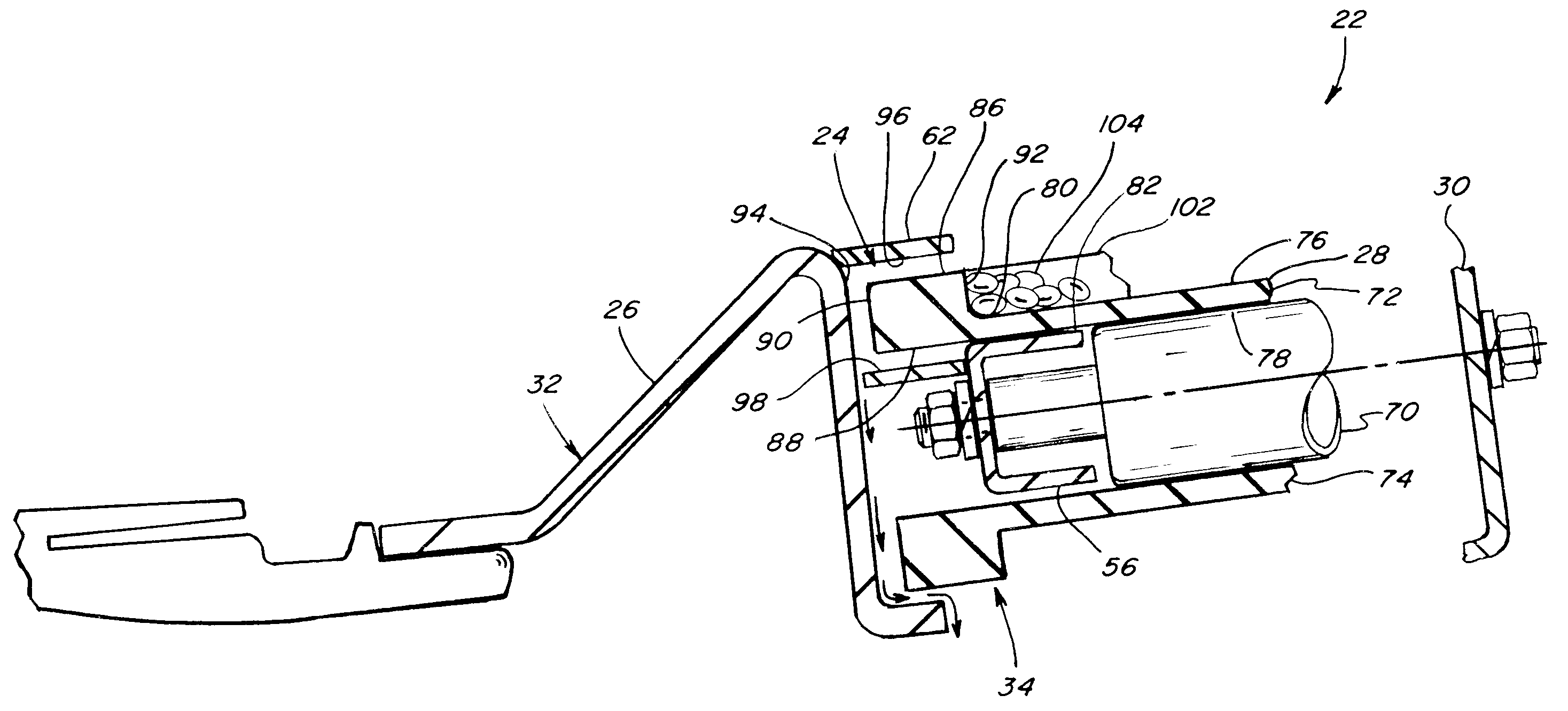
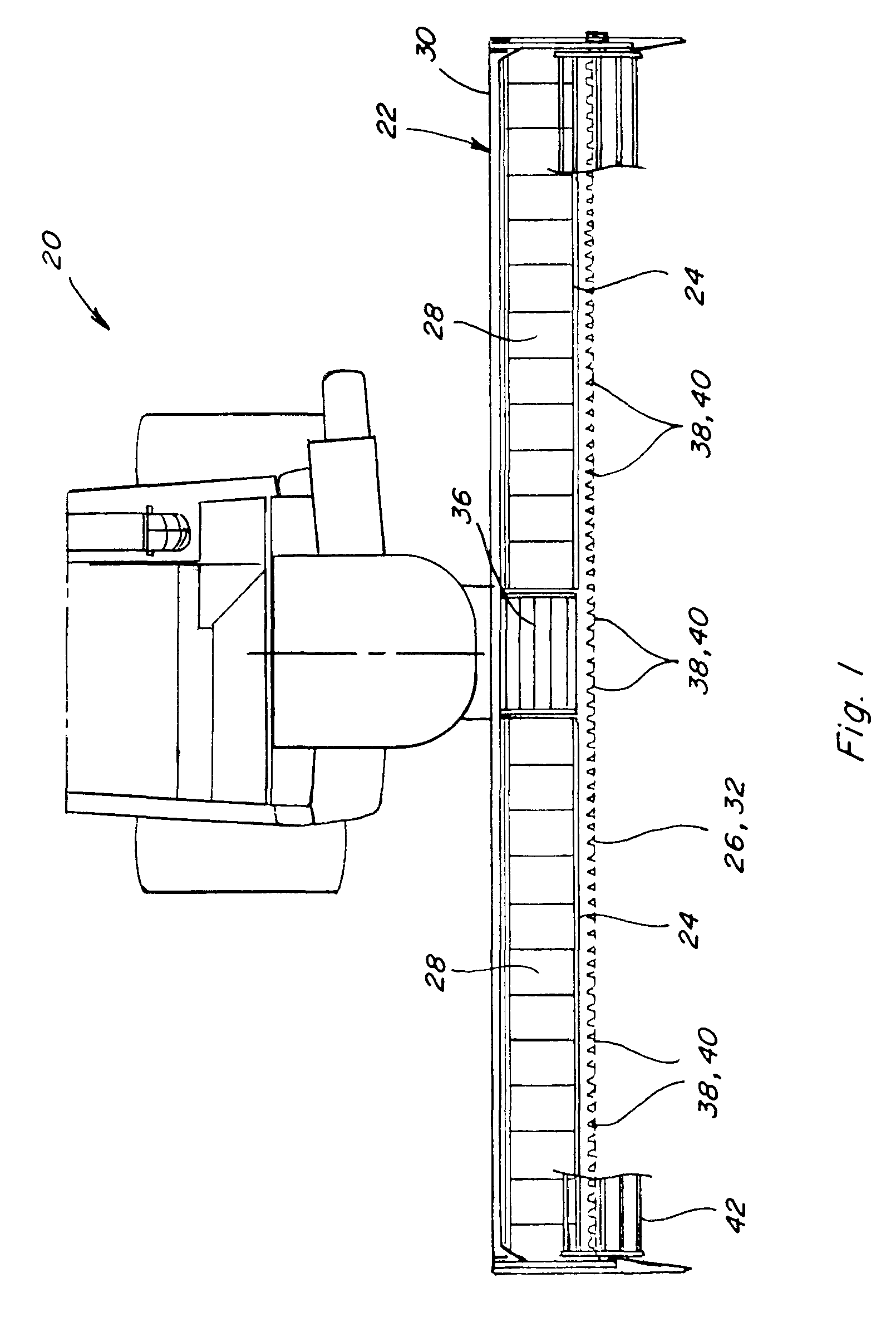
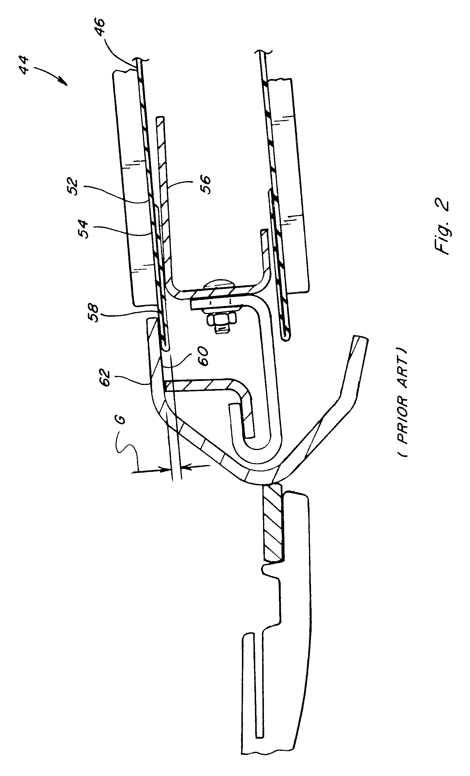
[0024]Referring now to the drawings, a preferred embodiment of the invention will be described, as will several prior art devices. In FIG. 1, a representative harvester 20, which is a combine harvester of well-known construction, is shown, including a draper header 22 incorporating a multiple sided cut crop barrier interface 24 between an elongate sidewardly extending cutter bar 26 and a front edge of an elongate sidewardly extending draper canvas 28 of header 22, which effectively prevents entry of cut crop and material carried thereby into the interior of the header, while reducing friction between the draper canvas and cutter bar, so as to provide better wearability and extended draper fabric life.

[0025]Header 22 comprises a frame 30, one element of which is shown extending forwardly from a rear support frame structure (not shown) to cutter bar 26. Frame 30 of header 22 can have a variety of forms, but will generally comprise a structure of sheet metal members configured for supp...


PUM


Abstract

The draper canvas of the header includes a strip of a resilient material that stands outwardly and forwardly of a front edge thereof and has an outer barrier surface, an inner barrier surface, and a front barrier surface received and contained in structure of a cutter bar and a front draper support plate having a plurality of barrier elements in face-to-face closely spaced relation with the barrier surfaces to form a multiple sided barrier interface between the cutter bar and draper fabric for excluding cut crop from the interior of the header. The strip runs within the container structure with minimal contact to reduce friction and wear.

Description

TECHNICAL FIELD[0001]This invention relates to a header for cutting and transporting a standing crop with a transverse leading cutter bar, and, more particularly, to header which provides a multiple sided barrier interface to prevent entry of cut crop between a front edge of a draper canvas and the cutter bar, which also advantageously reduces friction and resulting wear of the draper canvas.BACKGROUND ART[0002]Draper headers generally include a header frame, an elongate cutter bar along a front edge of the frame including a cutter bar beam which carries a plurality of knife guards for guiding reciprocating movement of a sickle knife across a front edge of the cutter bar. On the header is also mounted a draper assembly including a first and second draper guide roller each arranged at a respective end of the draper assembly spaced apart along the cutter bar with an axis of each roller extending substantially at right angles to the cutter bar, a draper canvas forming a continuous loop...

Claims


Application Information

Patent Timeline
IPC IPC(8): A01D43/00
CPCA01D57/20A01D61/002
Inventor RAYFIELD, JAMES F.CONROY, JOHN J.
Owner BLUE LEAF I P
Why Eureka
Try Eureka