Method of operating a hydraulic pressing unit, and hydraulic pressing unit having a hydraulic pump

a pressing unit and hydraulic technology, applied in the direction of press ram, forging presses, manufacturing tools, etc., can solve the problems of return valve closing and pressure drop

Inactive Publication Date: 2011-03-22
GUSTAV KLAUKE GMBH
View PDF10 Cites 26 Cited by
  • Summary
  • Abstract
  • Description
  • Claims
  • Application Information

AI Technical Summary

Benefits of technology

[0010]The control piston is preferably held in a non-actuated outflow position by the return flow alone, the control piston in this outflow position leaving a flow passage for the returning hydraulic medium. This flow passage is furthermore made of such a size that it does not produce any pressure losses with an adverse effect on the self-holding of the return valve. In the actuated pumping position of the pressing unit, on the other hand, the control piston leads to a shutting-off of the flow, i.e. of the return flow, accordingly initiation of a pressing operation at the same time brings about the displacement of the control piston into a shut-off position. This shutting-off alone leads to a pressure drop at the return valve, as a result of which the latter closes. The displacement of the control piston counter to the flow direction of the returning hydraulic medium as a result of the pressing unit being put into operation also brings about an intake of a partial amount of the hydraulic medium, which further helps to bring about the desired pressure drop for closing the return valve.
[0027]A configuration in which the control piston, part of the outflow line and part of the hydraulic line are formed in an insert part which is fitted as a whole into a bore-like continuation of the first sub-chamber also proves to be advantageous. This creates a compact unit, which is optionally able to be removed again and which makes it possible for the hydraulic pressing unit to be fitted according to choice with means for regulating the pressure drop in the course of the return of the hydraulic medium or for pressing units to be retrofitted with such means.

Problems solved by technology

As and when required, this sucks a partial amount out of the actual return path, which leads to the desired pressure drop.
Here too, this effect that is brought about on the return flow brings about a pressure drop, which results in the closing of the return valve.

Method used


Image

  • Method of operating a hydraulic pressing unit, and hydraulic pressing unit having a hydraulic pump
  • Method of operating a hydraulic pressing unit, and hydraulic pressing unit having a hydraulic pump
  • Method of operating a hydraulic pressing unit, and hydraulic pressing unit having a hydraulic pump

Examples


Embodiment Construction

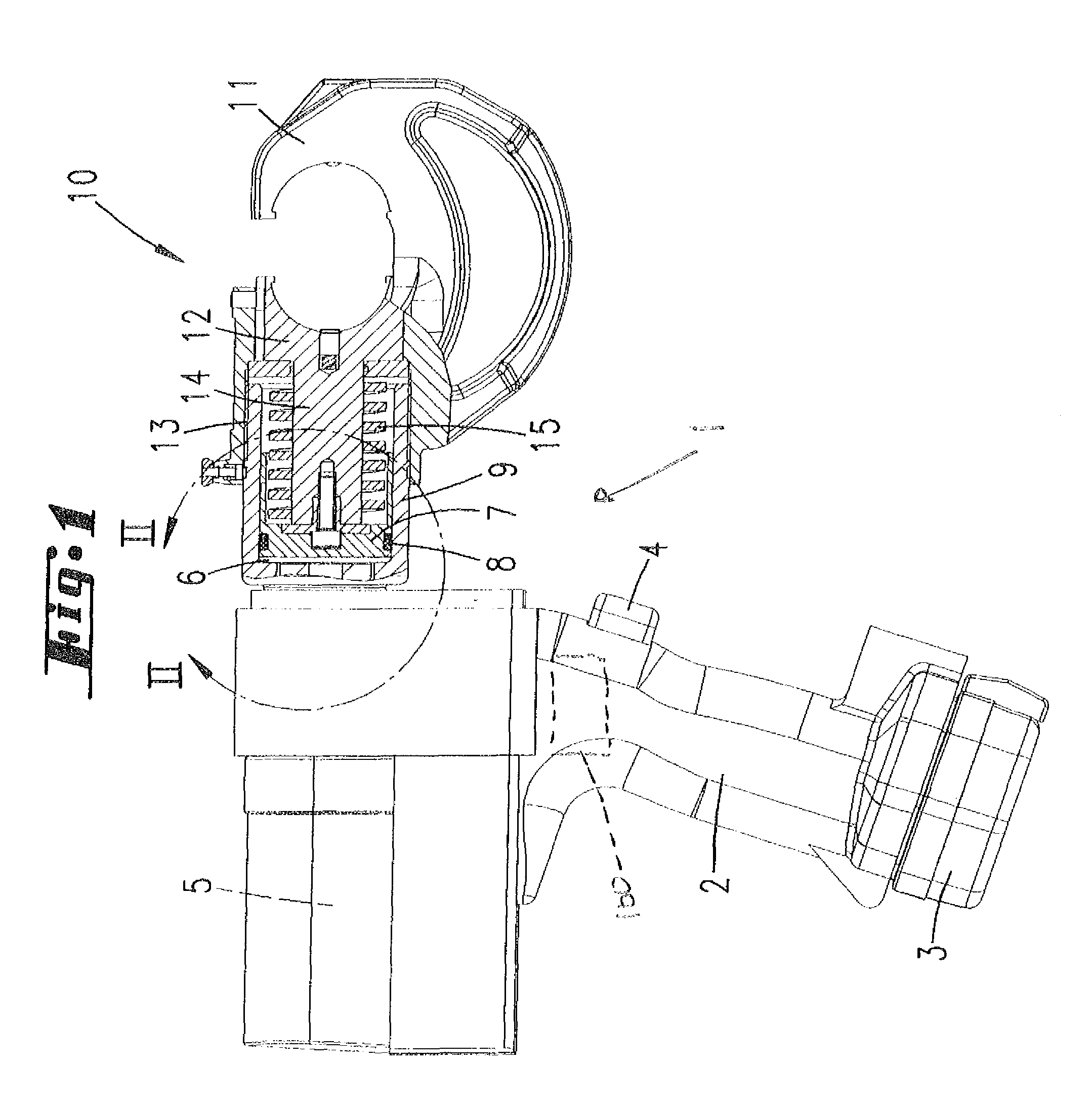
[0035]Shown and described, initially with reference to FIG. 1, is a hydraulic manual pressing unit 1, driven by an electric motor. Such a pressing unit is known from DE 199 44 229 A1, which is also covered by U.S. Pat. No. 6,718,870. The content of this patent application and United States patent is hereby incorporated in full in the disclosure of the present invention, including for the purpose of incorporating features of this patent application and United States patent in claims of the present invention.

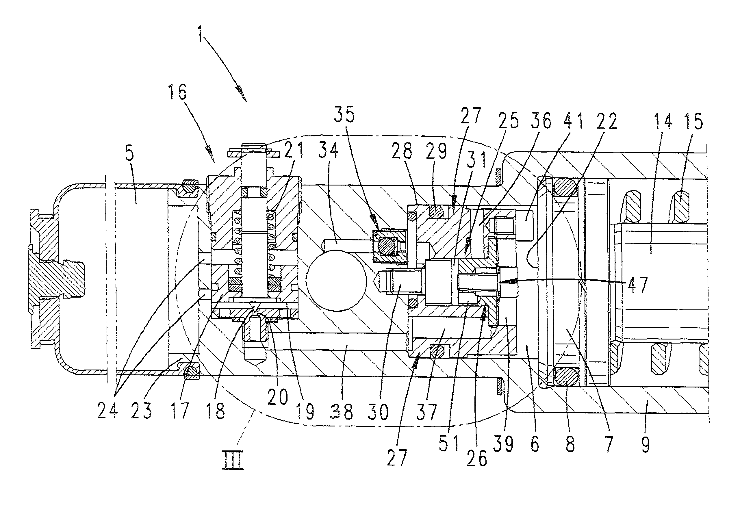
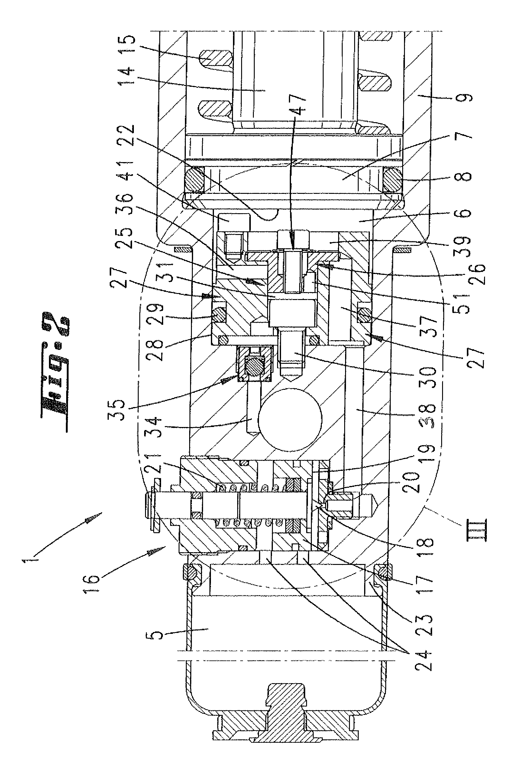
[0036]Disposed in the pressing unit 1 is an electric motor (not represented). The drive of this electric motor takes place by means of a storage battery 3 integrated in a handle 2. If a finger-operated switch 4 is actuated, hydraulic medium (oil) is pumped out of a supply chamber 5 into a hydraulic chamber 6, whereby a piston-like moving part 7 displaceably accommodated in the hydraulic chamber 6 is moved in the direction of a working end position.

[0037]The moving part 7 has a rad...


PUM

PropertyMeasurementUnit
pressure dropaaaaaaaaaa
pressureaaaaaaaaaa
pressureaaaaaaaaaa

Abstract

A hydraulic pressing unit includes a hydraulic pump, supply and hydraulic chambers, moving and stationary parts, a restoring spring, and a return valve provided within or attached to a housing. The moving part is displaced from a starting position into a pressing position as a result of filling the hydraulic chamber with a hydraulic medium from the supply chamber by using the hydraulic pump. The return valve is automatically displaced into an open position as a result of a hydraulic pressure corresponding to the pressing position, and the restoring spring moves the moving part. A piston acts on the flow of the hydraulic medium and lowers the pressure such that the return valve is displaced into the closed position.

Description

[0001]This patent application is a the National Stage filing of IB application number PCT / EP2007 / 055156, filed May 29, 2007, published as WO 07 / 141,156 on Dec. 13, 2007. IB application number PCT / EP2007 / 055156 claims priority from German Patent Application No. 10 2006 026 552.1 dated Jun. 8, 2006.FIELD OF THE INVENTION[0002]The invention relates in first instance to a method of operating a hydraulic pressing unit, in particular a manual pressing unit, the pressing unit having a hydraulic pump, a moving part, a stationary part and a return valve, furthermore the moving part being displaced into a pressing position by the buildup of a hydraulic pressure obtained by using the hydraulic pump for filling a hydraulic chamber with hydraulic medium from a supply chamber, furthermore the moving part being designed to move back automatically from the pressing position into an end position under the action of a restoring spring and the return valve being designed to close only after the pressu...

Claims


Application Information

Patent Timeline
Patent Type & Authority Patents(United States)
IPC IPC(8): B30B1/23
CPCB21J15/20B25B27/10B30B15/16
Inventor FRENKEN, EGBERT
Owner GUSTAV KLAUKE GMBH
Why Eureka
Try Eureka