
Siphon pump technology and apparatuses

a technology of siphon pump and pump body, applied in the direction of pump components, bends, thin material handling, etc., can solve the problems of inoperable metering siphon pump system, flow control, design complexity, self-priming,

Active Publication Date: 2014-07-01
OHAIR MICHAEL T
View PDF8 Cites 22 Cited by
  • Summary
  • Abstract
  • Description
  • Claims
  • Application Information

AI Technical Summary

Benefits of technology

The improved siphon pump technology and apparatuses described in the patent offer improvements in the safe and controlled transfer of liquids. The system components include an inlet anti-backflow valve, a system flow control valve, a metering chamber, an automatic regulating chamber, and a turbine. These improvements have resulted in a more precise and reliable pumping system with simplified design and operation. The invention has applications in food production, water management, and energy development.

Problems solved by technology

The prior art has problems related to self-priming, retention of prime, flow control, and design complexity.
Technical issues identified in U.S. Pat. No. 5,358,000 render the metering siphon pump system inoperable.
Deficiencies in the patent include the omission of key elements, inclusion of unnecessary components, complexity of the metering chamber, and inadequate priming and control methodologies.
The automatic timing apparatus to control metering involves a complex arrangement of multiple valves, mechanical systems, and magnetic devices that rely on critical timing for operation, limiting the feasibility for commercial applications.
The prototype system flow control valve has problems associated with massive weight and size, limited control functions, complexity of design and operation, and manual operation only.
Hydropower technologies have limited scalability, risk of functionality and / or flood damage due to proximity of supply source, lack of prime retention, limited flow control, and required priming at system shut down.

Method used


Image

  • Siphon pump technology and apparatuses
  • Siphon pump technology and apparatuses
  • Siphon pump technology and apparatuses

Examples


Embodiment Construction

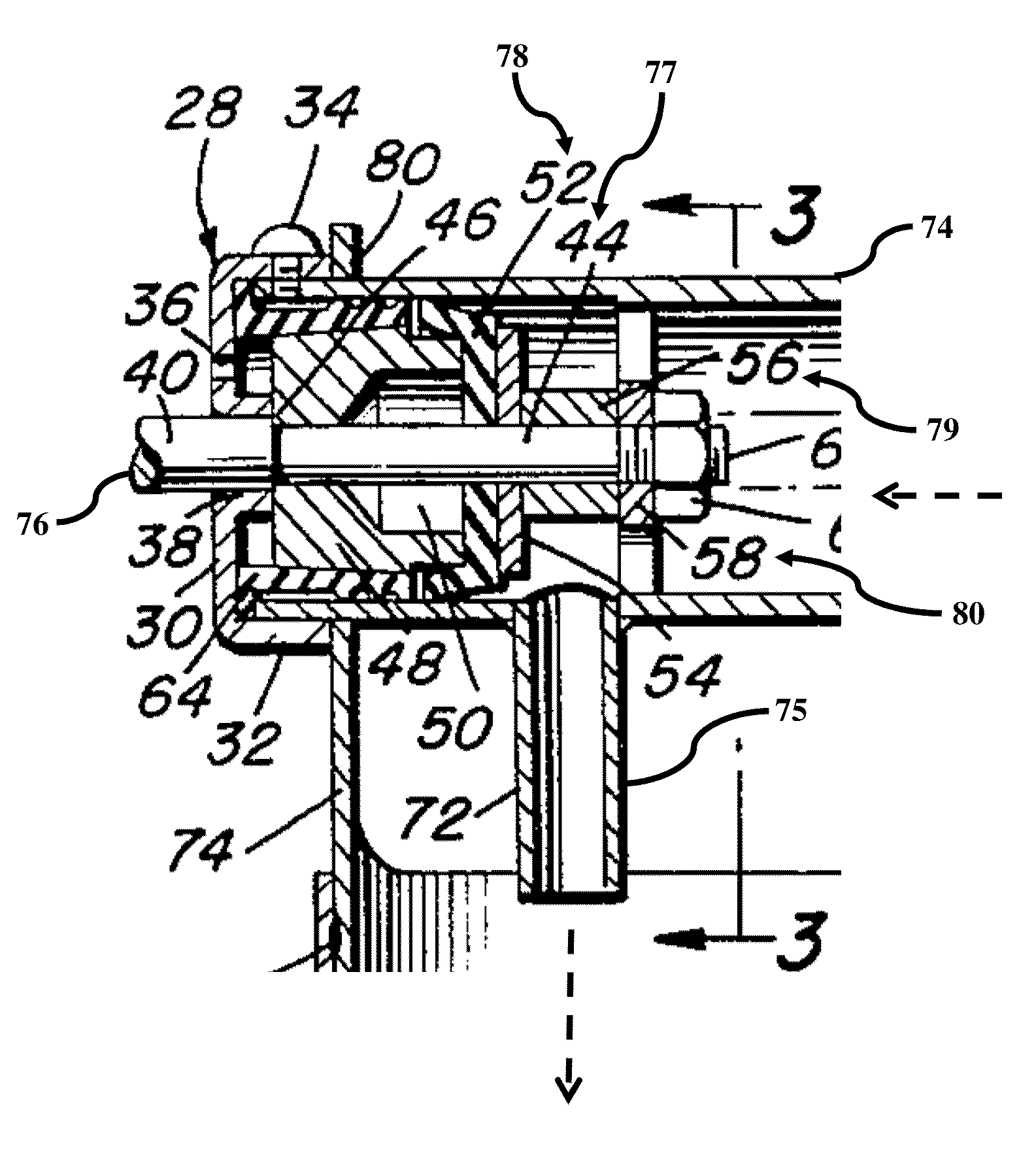
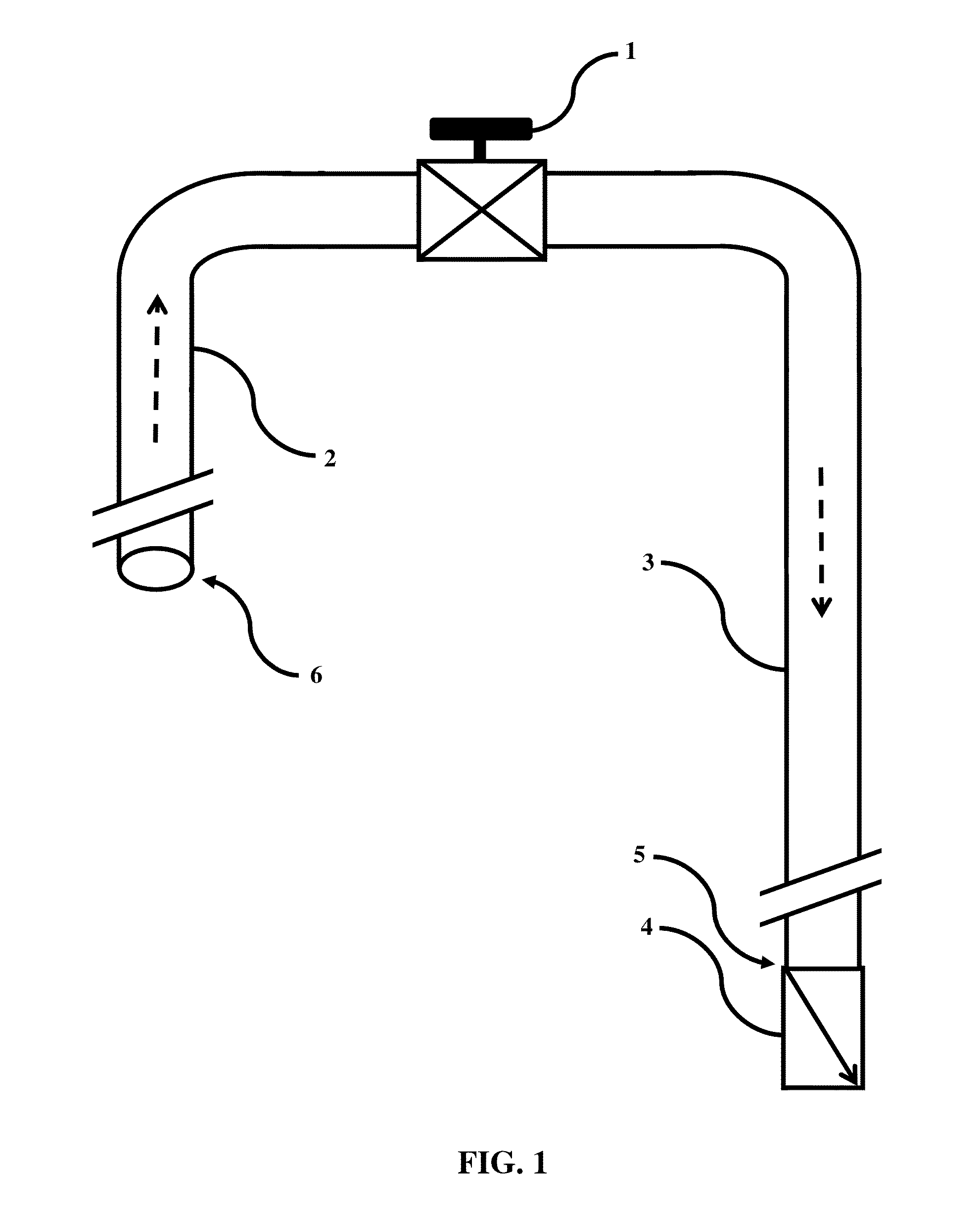
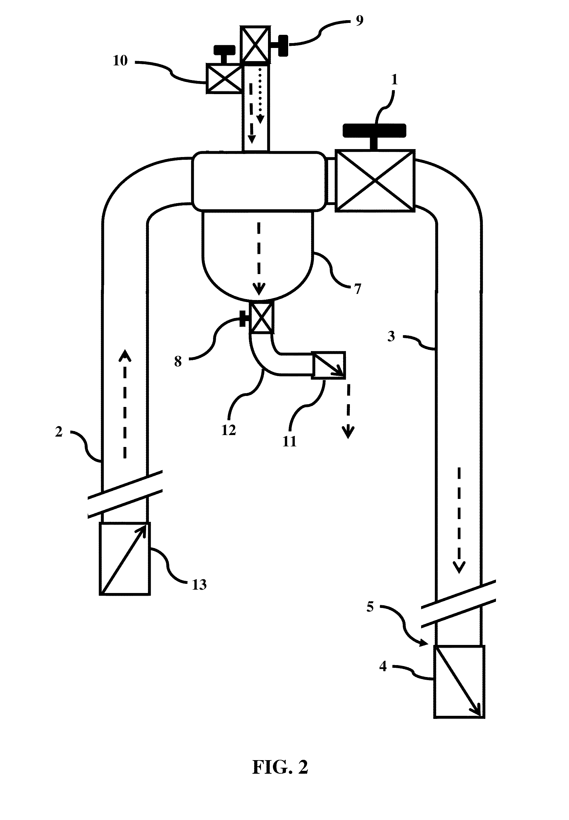
[0067]FIGS. 8 through 12 illustrate the following detailed descriptions for an Improved Siphon Pump Technology and Apparatuses presented in Claims 1 through 5, respectively.

[0068]FIG. 8 illustrates an improved siphon system having an anti-backflow valve 39 at the first siphon conduit 2 inlet for full-time prime retention to maintain system readiness. The system comprises a two-way system flow control valve 1 arranged between the first siphon conduit 2 having an anti-backflow valve 39 within the inlet, and a second siphon conduit 3 having an anti-backflow valve 4 within the outlet. Opening and closing of the inlet 39 and outlet 4 anti-backflow valves automatically responds to the opening and closing of the two-way system flow control valve 1. Priming is accomplished by placing the inlet of the first siphon conduit 2 in a liquid supply source and operating a suction device to withdraw air via the second siphon conduit 3 outlet until the system is filled with liquid, or vertically movi...


PUM


Abstract

Apparatuses to enable single-point valve control of siphons, siphon pumps, metering siphon pumps, and turbine siphon pumps include terminal anti-backflow valves, a system flow control valve, a metering chamber, a self-regulating chamber, and a siphon turbine. The terminal anti-backflow valves provide automatically closable systems without further priming after an initial prime. The system flow control valve consolidates functions for priming, pumping, dispensing, and siphon flow regulation to provide single-point valve control. The metering chamber operated by a single-point system flow control valve enables periodic dispensing of liquid above a supply source. The self-regulating chamber controls a single-point system flow control valve to regulate a metering chamber for periodic dispensing. The siphon turbine provided with terminal anti-backflow valves and regulated by a single-point system flow control valve enables hydropower production. Benefits include precision control, single-point operation, safety, new applications, energy savings, installations without power facilities, and a renewable clean energy technology.

Description

[0001]A non-provisional utility patent application for an Improved Siphon Pump Technology and Apparatuses related to single-point valve control for closable siphon pump systems is submitted Pro Se by John T. Carter, a USA citizen born Nov. 3, 1939, residing at 643 Keenon Road, Harrodsburg, Ky., 40330-8619; contact via email (johntcarter@usa.com) or cell phone (859-325-3271).BACKGROUND OF THE INVENTION[0002]1. Field of the Invention[0003]The field of the invention encompasses Class 137 for flowable materials, Sub-Class 123 for siphons, and Class 415 for rotary pumps and Sub-Class 80 for runners. The invention relates to improvements in owned U.S. Pat. No. 5,358,000 and related prior art for a siphon pump technology that includes system components and apparatuses comprising an inlet anti-backflow valve, a system flow control valve, a metering chamber, an automatic regulating chamber, and a turbine. Improvements benefit the safe and controlled transfer of liquids such as water, chemica...

Claims


Application Information

Patent Timeline
Patent Type & Authority Patents(United States)
IPC IPC(8): F04F10/00
CPCF04F10/00Y10T137/2808Y10T137/2768Y10T137/289Y10T137/2849
Inventor CARTER, JOHN, T.
Owner OHAIR MICHAEL T
Learn More