Steering shaft support structure of motor-driven steering assist apparatus
a technology of steering shaft and supporting structure, which is applied in the direction of power steering steering, electric steering, vehicle components, etc., can solve the problems of displacement affecting the torque sensor, the steering shaft and the input shaft cannot be connected, and the axial displacement cannot be accommodated, so as to improve the workability of connecting
- Summary
- Abstract
- Description
- Claims
- Application Information
AI Technical Summary
Benefits of technology
Problems solved by technology
Method used
Image
Examples
embodiment 1
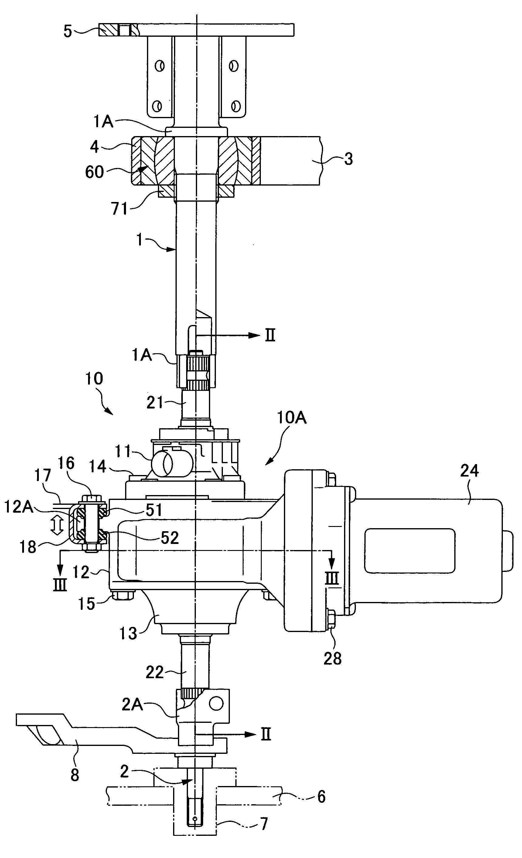
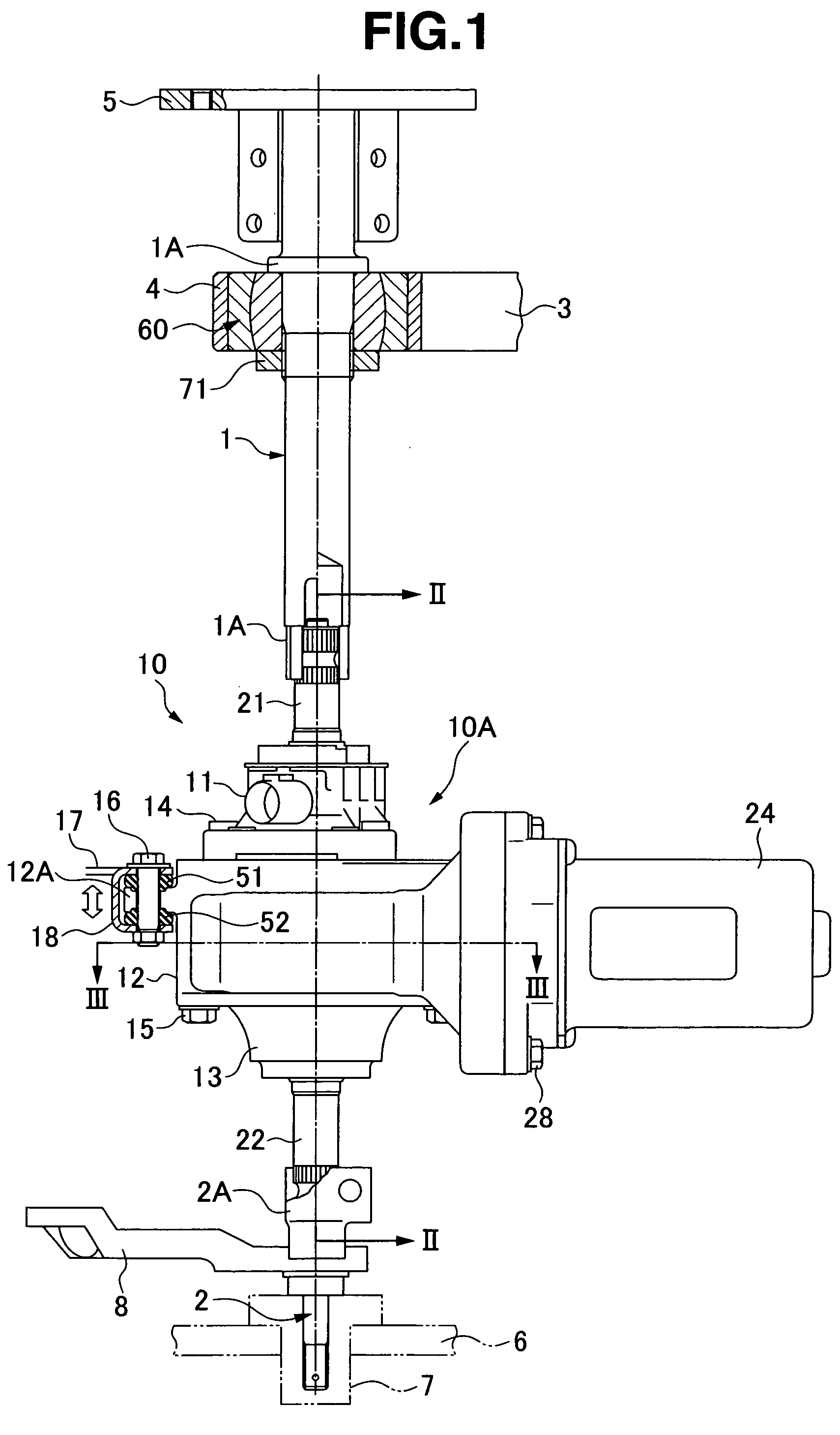
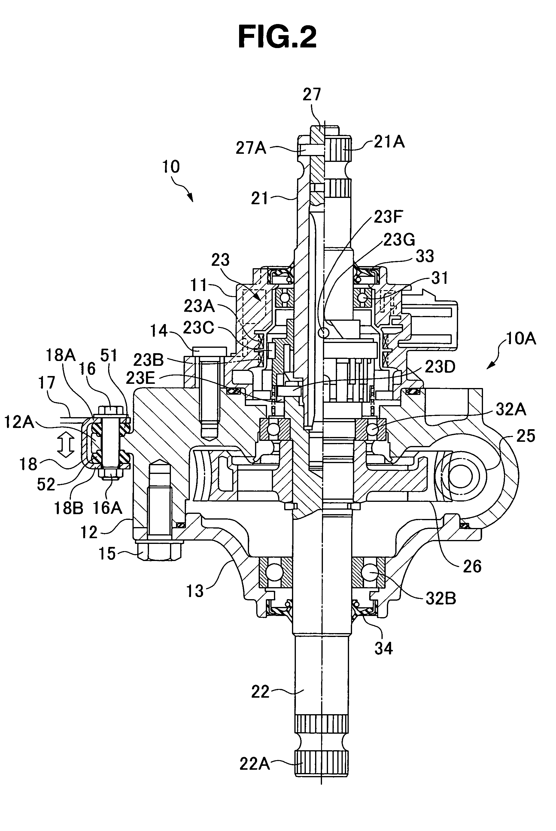
[0027]A motor-driven steering assist apparatus 10 may be applied to a rough road traveling vehicle, for example, a buggy vehicle, a snowmobile and the like. The apparatus is interposed between a steering wheel side steering shaft 1 and a tire wheel side steering member 2, as shown in FIG. 1, and assists steering force applied to the steering wheel by a driver on the basis of a generated torque of an electric motor 24.
[0028]The motor-driven steering assist apparatus 10 is structured such that the steering shaft 1 is rotatably supported to an upper vehicle body side stay 3 via a bearing mentioned below by a support member 4, and a steering wheel attaching member 5 is fixed to an upper end portion. The tire wheel side steering member 2 is rotatably supported to a lower vehicle body side stay 6 via a bearing by a support member 7, and a pitman arm 8 is fixed to an intermediate portion thereof. The pitman arm 8 is coupled to a front wheel via right and left tie rods. The upper vehicle bo...
embodiment 2
[0044]A description will be given of a motor-driven steering assist apparatus 10 in accordance with an embodiment 2 (FIGS. 5 and 6).
[0045]In this case, the same reference numerals are attached to elements in the embodiment 2 substantially the same as those of the embodiment 1, and a description thereof will be omitted.
[0046]In the motor-driven steering assist apparatus 10, in order to prevent the load in the axial direction for pulling up or pushing down applied to the steering shaft 1 from the steering wheel (reference symbol F in FIG. 6 indicates the pull-up load) from being applied to the torque sensor 23 via the input shaft 21, the steering shaft 1 is supported to a bearing 160 of the support member 4 attached to the upper vehicle body side stay 3 so as to be rotatable and immobile in the axial direction.
[0047]The bearing 160 includes, for example, an angular contact ball bearing which can simultaneously bear the radial load and the thrust load of the steering shaft 1, as shown ...
embodiment 3
[0053]A description will be given of a motor-driven steering assist apparatus 10 in accordance with an embodiment 3 (FIGS. 7 and 8).
[0054]In this case, the same reference numerals are attached to elements in the embodiment 3 substantially the same as those of the embodiment 1, and a description thereof will be omitted.
[0055]In accordance with the motor-driven steering assist apparatus 10, it may be desirable to improve connecting workability between the steering shaft 1 and the input shaft 21 of the motor-driven steering assist apparatus 10, and prevent the pull-up or push-down load in the axial direction (reference symbol F in FIG. 7 indicates the pull-up load) applied to the steering shaft 1 from the steering wheel from being applied to the torque sensor 23 via the input shaft 21, while supporting the steering shaft to the support member 4 of the vehicle body side stay 3 and supporting the motor-driven steering assist apparatus 10 to the vehicle body side bracket 17. A spherical s...
PUM
 Abstract
Description
Claims
Application Information
 - R&D
- Intellectual Property
- Life Sciences
- Materials
- Tech Scout
- Unparalleled Data Quality
- Higher Quality Content
- 60% Fewer Hallucinations
Browse by: Latest US Patents, China's latest patents, Technical Efficacy Thesaurus, Application Domain, Technology Topic, Popular Technical Reports.
© 2025 PatSnap. All rights reserved.Legal|Privacy policy|Modern Slavery Act Transparency Statement|Sitemap|About US| Contact US: help@patsnap.com


