
Antipersonnel barrier system

a technology of anti-personnel and barrier, which is applied in the direction of barbed wire, applications, ways, etc., can solve the problems of misalignment of the barrier, inability to achieve or retain the desired deployed configuration, and the barrier may be overextended or underextended, so as to provide horizontal and vertical stability to the coil

Active Publication Date: 2011-03-22
ALLIED TUBE CONDUIT
View PDF15 Cites 7 Cited by
  • Summary
  • Abstract
  • Description
  • Claims
  • Application Information

AI Technical Summary

Benefits of technology

[0008]In accordance with the present disclosure, an antipersonnel barrier system is provided which includes at least one concertina coil and a plurality of support members. Each of the support members is secured to the at least one concertina coil to provide horizontal and vertical stability to the coils.
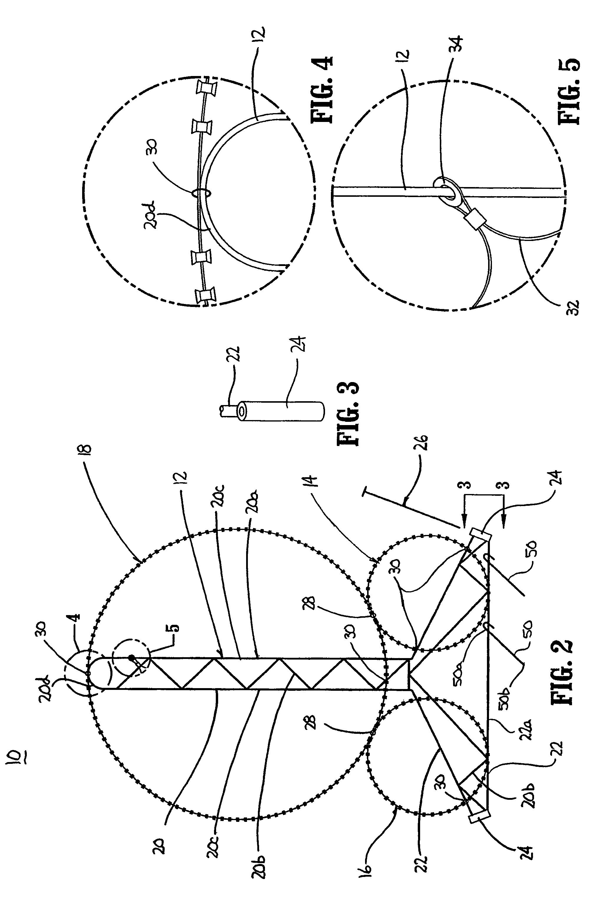
[0009]In one embodiment, the antipersonnel barrier system includes three coils including two base coils and one top coil. It is envisioned that greater or fewer coils may be provided. The support members each include a base section and a vertical section. The vertical section extends to at least substantially the height of the top coil and is attached thereto to provide vertical stability to the barrier system. The base section of the support member can be attached to the base coils at two locations to provide horizontal stability to the barrier system.
[0010]In one embodiment, each of the support members is attached to adjacent support members by a cable which prevents separation of adjacent support members beyond a predetermined distance, e.g., 9 feet. The cable prevents over extension of the barrier system.
[0011]Each of the base coils can be secured to the top coil to provide added stability to the barrier system. Anchoring structure including stakes, hooks or the like can be provided to secure or anchor the support members and / or coils to a support surface, e.g., ground.

Problems solved by technology

One problem associated with known rapidly deployable barriers is that during and / or after deployment, the barrier becomes misaligned and does not attain or retain a desired deployed configuration.
For example, during and / or after deployment, the barrier may be overextended or underextended and / or the concertina coils may sag or become misaligned.
As a result of such misalignment, the effectiveness of the barrier is reduced.

Method used


Image

  • Antipersonnel barrier system
  • Antipersonnel barrier system
  • Antipersonnel barrier system

Examples


Embodiment Construction

[0027]Embodiments of the presently disclosed antipersonnel barrier system and its method of deployment will now be described in detail with reference to the drawings in which like reference numerals designate identical or corresponding elements in each of the several views.

[0028]As used herein, the term concertina coils means any wire or coil for resisting passage including barbed wire, razor wire, electrified wire, barbed tape and any other coil with or without structure for inflicting bodily harm.

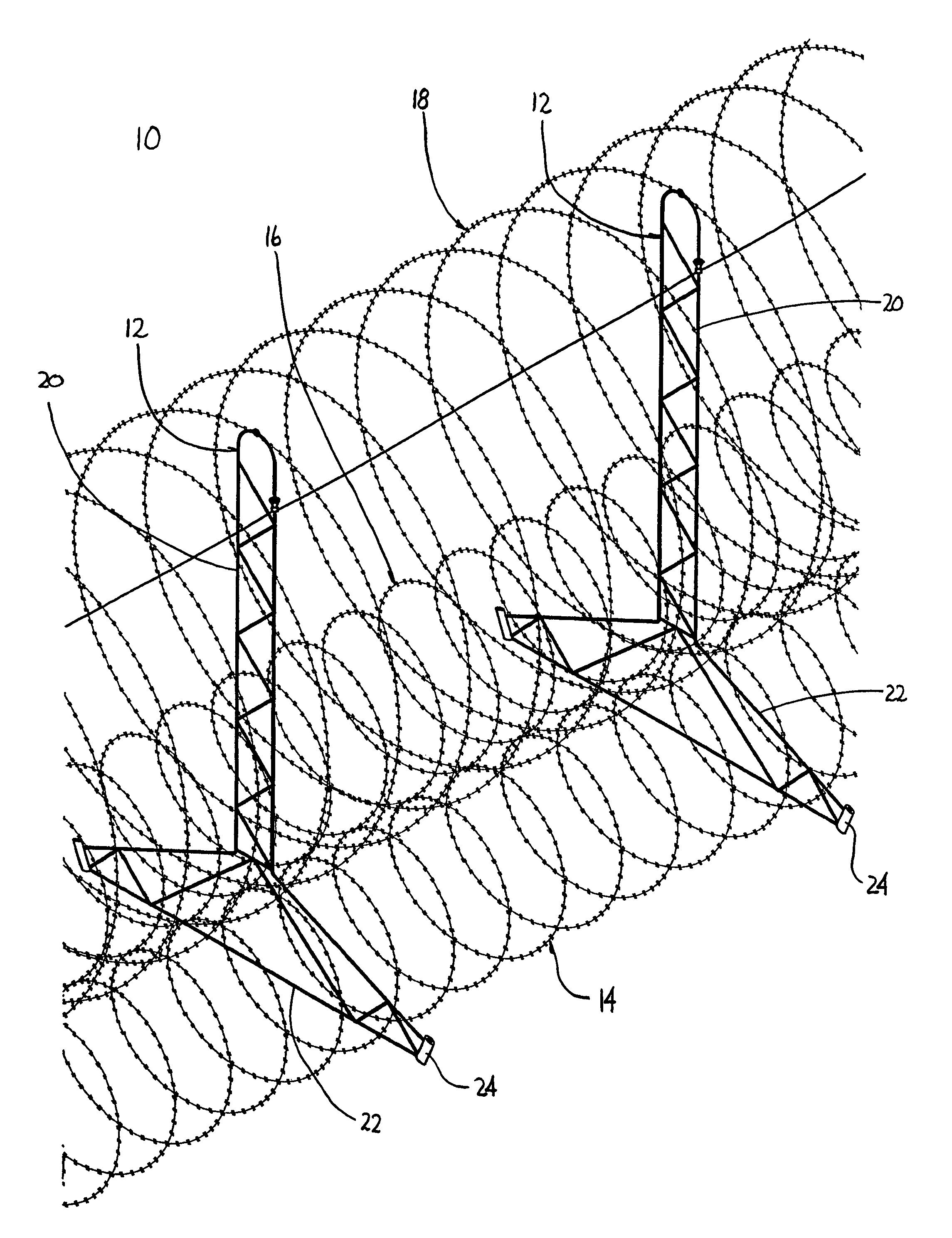
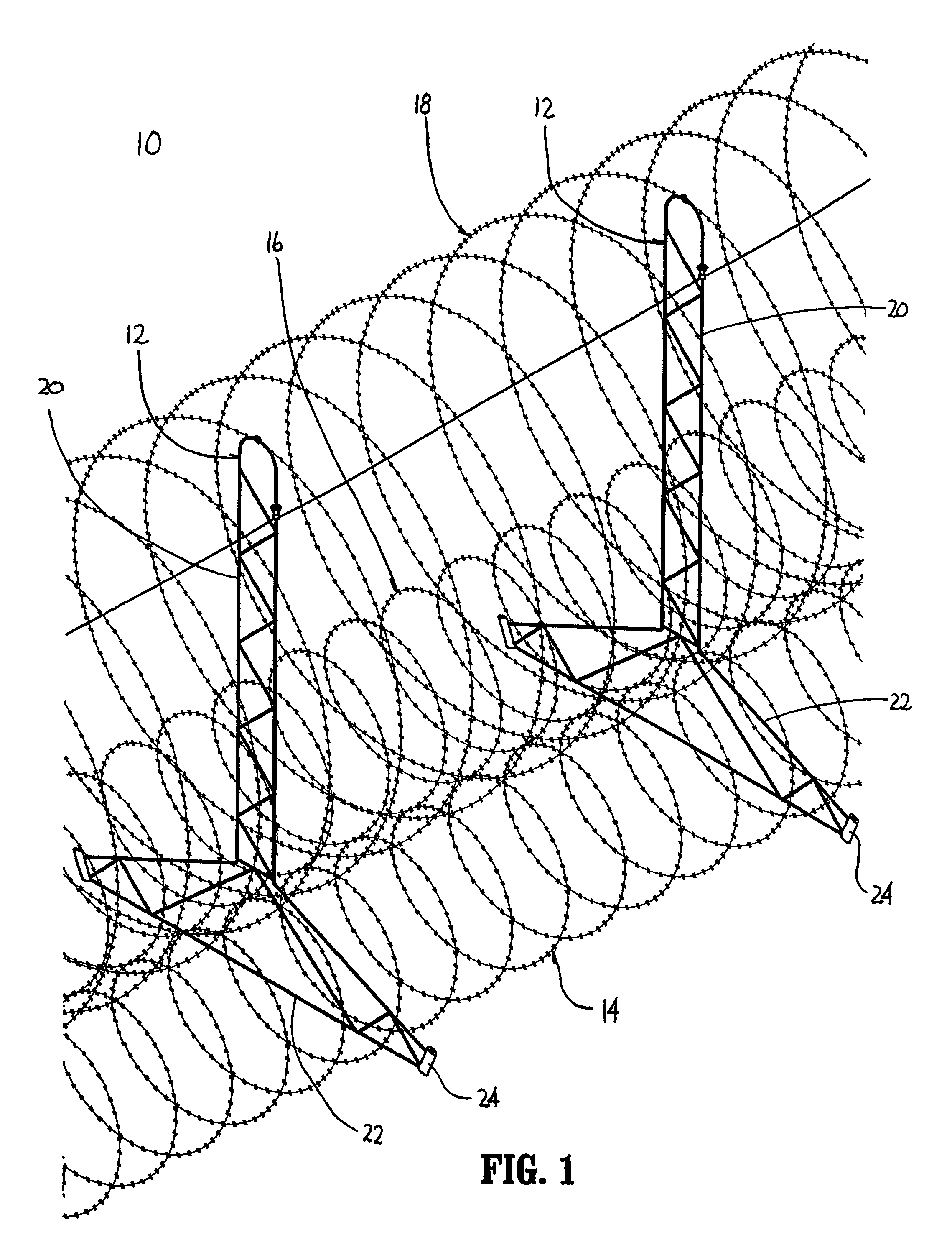
[0029]FIG. 1 illustrates one embodiment of the presently disclosed antipersonnel barrier system shown generally as 10. Antipersonnel barrier system 10 includes at least one concertina coil and a plurality spaced support members 12. In this embodiment, three concertina coils 14, 16 and 18 are provided. It is envisioned that barrier 10 may include one or more coils, e.g., 5, 6, 7 etc. Coils 14 and 16 are positioned in axial alignment to define a base of barrier 10. Coil 18 is positioned on ...


PUM


Abstract

An antipersonnel barrier system includes at least one concertina coil and a plurality of spaced support members. Each of the support members includes a base section and a vertical section. Each of the concertina coils is secured to the support members to provide a horizontally and vertically stabilized barrier. A length limiting cable is provided to limit the length of spacing between adjacent support members. The support members can include anchoring structure for securing the support members to a support surface. In one embodiment, the concertina coils include two small diameter base coils and a top coil positioned on the base coils.

Description

[0001]This application claims priority from U.S. provisional application Ser. No. 60 / 665,782 filed Mar. 28, 2005, the entire contents of which is incorporated herein by reference in its entirety.BACKGROUND[0002]1. Technical Field[0003]The present disclosure relates to a transportable barrier which can be rapidly deployed. More specifically, the present disclosure relates to a transportable barrier which includes support structure to facilitate rapid stable deployment.[0004]2. Background of Relate Art[0005]Transportable barriers for defining a confined or protected area which can be rapidly deployed are well known. Typically, such barriers include one or more concertina coils which are stored in a compressed fashion and axially extended to deploy. The concertina coils may be constructed from a variety of diameters and include a variety of barbed configurations.[0006]One problem associated with known rapidly deployable barriers is that during and / or after deployment, the barrier becom...

Claims


Application Information

Patent Timeline
Patent Type & Authority Patents(United States)
IPC IPC(8): B21F25/00E04H17/02
CPCE01F13/022F41H11/08
Inventor MAJOR, ROBERT W.SHIPLEY, DONALD SCOTT
Owner ALLIED TUBE CONDUIT
Learn More